Lock assembly with anti-panic feature and associated method

a technology of anti-panic feature and lock assembly, which is applied in the direction of latching locks, building locks, constructions, etc., can solve the problems of time-consuming and expensive planning and installation of door and lock assembly, and the need for time-consuming and labor-intensive universal lock assembly

Active Publication Date: 2011-04-19
ROCKWELL SECURITY
View PDF43 Cites 22 Cited by
  • Summary
  • Abstract
  • Description
  • Claims
  • Application Information

AI Technical Summary

Benefits of technology

[0007]The lock assembly includes adjustable latch and deadbolt assemblies. The latch assembly has a latch member that is configured to be adjusted by a rotation of the handles between an extended position and a retracted position to thereby selectively engage the keeper structure. The deadbolt assembly has a deadbolt member that is configured to be adjusted by a rotation of a deadbolt handle and a key lock mechanism between an extended position and a retracted position to thereby selectively engage the keeper structure. In addition, the lock assembly provides an anti-panic feature from a select side of the door. For example, a selective connection feature can be configured to be selectively installed in first and second configurations to thereby selectively link the first or second handles to the deadbolt assembly. In the first configuration, the first handle is configured to adjust the deadbolt assembly to an unlocked configuration while the second handle is locked, i.e., prevented from rotating. In the second configuration, the second handle is configured to adjust the deadbolt assembly to an unlocked configuration while the first handle is locked. Thus, the anti-panic feature of the lock assembly can facilitate the unlocking of the door from one side thereof and, further, the anti-panic feature can be provided at either side of the door, e.g., to accommodate different types of installations having different door configurations.
[0010]For example, each of the plates and the lock link can define an aperture for receiving a lock screw, and the lock screw can be configured to selectively connect a respective one of the plates to the lock link so that the lock link is configured to rotate with the respective plate and the lock link does not rotate with the other plate. In addition, the housing and the lock link can define another pair of corresponding apertures for receiving the lock screw so that the lock screw can be removed from the plates and disposed through the pair of corresponding apertures to fix the lock link to the housing in a third configuration to thereby prevent a rotation of the lock link relative to the housing.
[0013]According to another embodiment, the present invention can provide a method of providing an anti-panic lock assembly. In one such method, the latch assembly and the deadbolt assemblies are provided, each having the latch and deadbolt members, respectively. A selective connection feature can be selectively installed in one of first and second configurations to thereby selectively link one of the first and second handles to the deadbolt assembly, wherein in the first configuration the first handle is configured to adjust the deadbolt assembly to an unlocked configuration while the second handle is locked, and in the second configuration the second handle is configured to adjust the deadbolt assembly to an unlocked configuration while the first handle is locked, such that the lock assembly is configured to be installed to provide an anti-panic feature from a select side of the door.

Problems solved by technology

Alternatively, the installer can use a universal lock assembly that is adaptable for use in either configuration; however, such a universal lock assembly typically requires time, effort, and expertise on the part of the installer to adapt the lock assembly as necessary.
Thus, the planning and installation of the door and lock assembly can be time-consuming and expensive.

Method used


Image

  • Lock assembly with anti-panic feature and associated method
  • Lock assembly with anti-panic feature and associated method
  • Lock assembly with anti-panic feature and associated method

Examples


Embodiment Construction

[0032]The present inventions now will be described more fully hereinafter with reference to the accompanying drawings, in which some, but not all embodiments of the inventions are shown. Indeed, these inventions may be embodied in many different forms and should not be construed as limited to the embodiments set forth herein; rather, these embodiments are provided so that this disclosure will satisfy applicable legal requirements. Like numbers refer to like elements throughout.

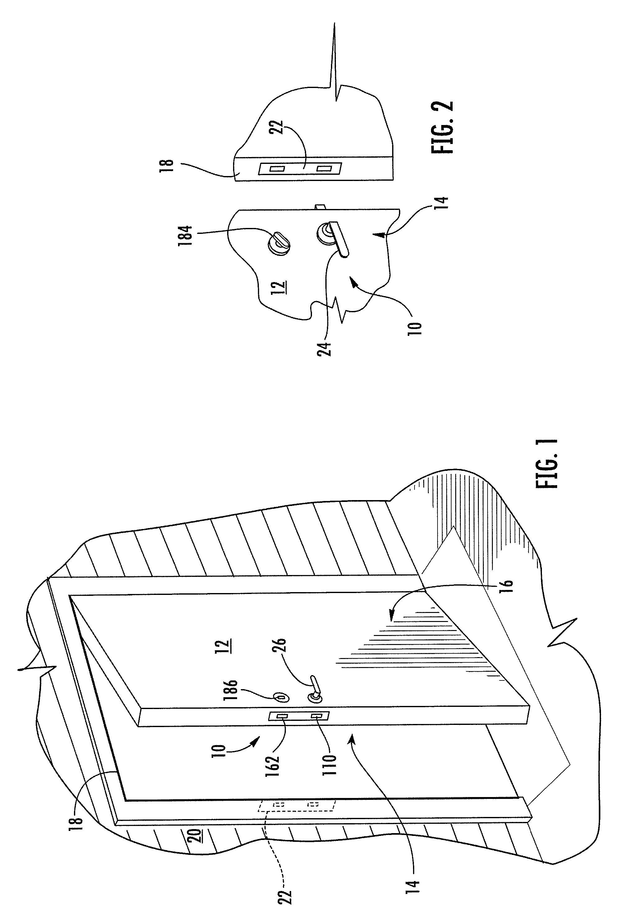
[0033]The lock assembly of the present invention is typically provided in a door and used to selectively secure the door in a closed, i.e., locked, position. Referring to the drawings and, in particular, to FIGS. 1 and 2, there is shown a lock assembly 10 of the present invention disposed in a door 12, as seen from an exterior side 16 of the door 12 (FIG. 1) and an interior side 14 of the door 12 (FIG. 2). As illustrated, the door 12 can be a swinging door that is mounted by hinges in a door frame 18 in a wall...


PUM


Abstract

An anti-panic lock assembly for a door and associated methods are provided. The lock assembly can be used to secure the door to a keeper structure mounted in a jamb of a door frame so that the assembly can be adjusted by first and second handles extending from the opposite sides of the door. The lock assembly generally includes a latch assembly with a latch member and a deadbolt assembly with a deadbolt member for engaging the keeper structure. The latch member is configured to be adjusted by a rotation of the handles between its extended and retracted positions. The deadbolt member is configured to be adjusted by a rotation of a deadbolt handle and a key lock mechanism between its extended and retracted positions. The assembly can be installed to provide an anti-panic feature from a select side of the door, by using a selective connection feature to selectively link one of the handles to the deadbolt assembly. In a first configuration, the first handle can be configured to adjust the deadbolt assembly to an unlocked configuration while the second handle is locked. In a second configuration, the second handle can be configured to adjust the deadbolt assembly to an unlocked configuration while the first handle is locked.

Description

CROSS REFERENCE TO RELATED APPLICATIONS[0001]This application is related to commonly owned copending Provisional Application Ser. No. 60 / 826,159, filed Sep. 19, 2006, incorporated herein by reference in its entirety, and claims the benefit of its earlier filing date under 35 U.S.C. 119(e).FIELD OF THE INVENTION[0002]The present invention relates to a lock assembly such as is typically used for securing a door and, more particularly, relates to a lock assembly that can be adapted to provide an anti-panic feature for unlocking the assembly.BACKGROUND OF THE INVENTION[0003]One conventional lock assembly for use on an exterior swinging door includes a latch and a deadbolt. The latch is configured to be adjusted by a door handle, such as a door knob, and the lock is configured to be adjusted by a lock handle or a key. Both the latch and the deadbolt are adjustable between extended and retracted positions. In the extended position, the latch and deadbolt extend from the door and engage a ...

Claims


Application Information

Patent Timeline
Patent Type & Authority Patents(United States)
IPC IPC(8): E05B59/00
CPCE05B59/00E05B65/1086E05B63/16Y10T70/5226Y10T70/8946Y10T292/0908Y10T70/8541Y10T292/57Y10T70/5159
Inventor POLETTI, ANGELO
Owner ROCKWELL SECURITY
Why Eureka
Try Eureka