Display apparatus and method for hands free operation that selects a function when window is within field of view

a display and function technology, applied in the field of display apparatuses, can solve the problems of low accuracy in estimating the direction of the user, high hardware cost of the eye camera and a light source, and high computing cost of image processing used to estimate, etc., and achieve low accuracy in estimating the direction the user is looking, the hardware cost is high, and the accuracy is low

Inactive Publication Date: 2011-04-19
PANASONIC CORP
View PDF9 Cites 272 Cited by
  • Summary
  • Abstract
  • Description
  • Claims
  • Application Information

AI Technical Summary

Benefits of technology

[0009]In order to overcome the aforementioned problem, an object of the present invention is to provide a display apparatus which enables high-accuracy hands-free operation while adopting a low-cost configuration.
[0039]As can be seen from the above description, with the display apparatus according to the present invention, since the user cannot see part of a display element, when the user looks at the display element, the user's head moves automatically. Consequently, the display element displayed in the direction of head orientation change is selected and a predetermined process related to the selected display element is executed. This enables high-accuracy, hands-free operation while adopting a low-cost configuration which only needs to detect the direction of head orientation change.Further Information about Technical Background to this Application

Problems solved by technology

When the two methods are compared, the method which uses an eye camera has a problem in that it involves high hardware costs for the eye camera and a light source as well as high computing costs for image processing used to estimate the point of regard.
On the other hand, the method which uses an angular velocity sensor has a problem in that it has a relatively low accuracy in estimating the direction user is looking in although it has the advantage of involving relatively low hardware costs and computing costs.
The reason for the low accuracy is that when the user moves only his / her eyeballs without moving his / her head, the angular velocity sensor cannot detect the eyeball movements.
In this way, the method which uses an angular velocity sensor has a problem in that it cannot accurately find the display element watched by the user out of multiple display elements displayed on the screen of an HMD.

Method used


Image

  • Display apparatus and method for hands free operation that selects a function when window is within field of view
  • Display apparatus and method for hands free operation that selects a function when window is within field of view
  • Display apparatus and method for hands free operation that selects a function when window is within field of view

Examples


first embodiment

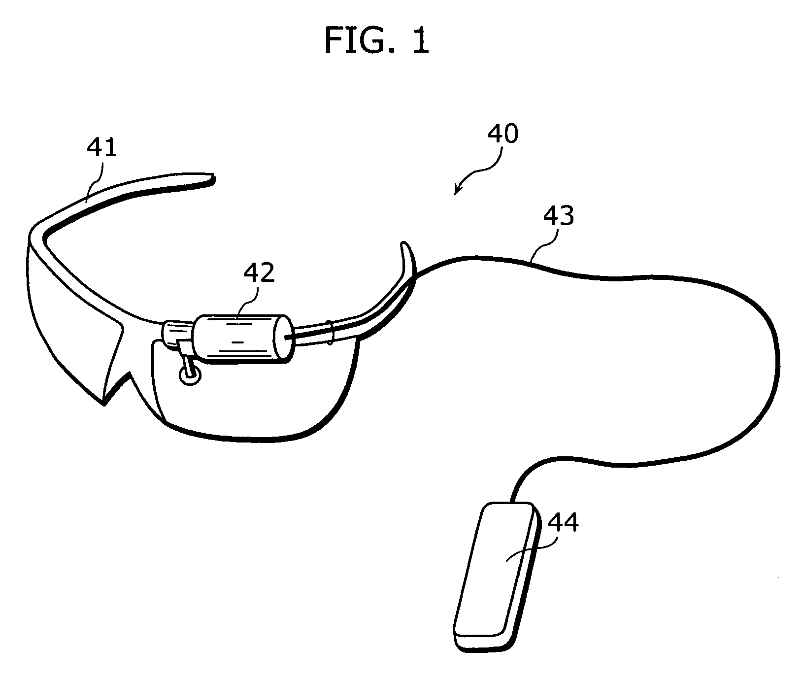
[0062]FIG. 1 is an external view of a display apparatus according to a first embodiment of the present invention. The first embodiment illustrates an example in which an HMD 40 is used as a display apparatus.

[0063]The HMD 40 is a display apparatus mounted on the head of a user. As shown in the figure, it consists of ordinary glasses 41 on which a small projector 42 is mounted. Image data, power, and the like are sent to the projector 42 from a main body 44 via a cable 43. The image data sent to the projector 42 is projected onto a display prism mounted along lenses of the glasses 41 at a viewing angle of around 27.

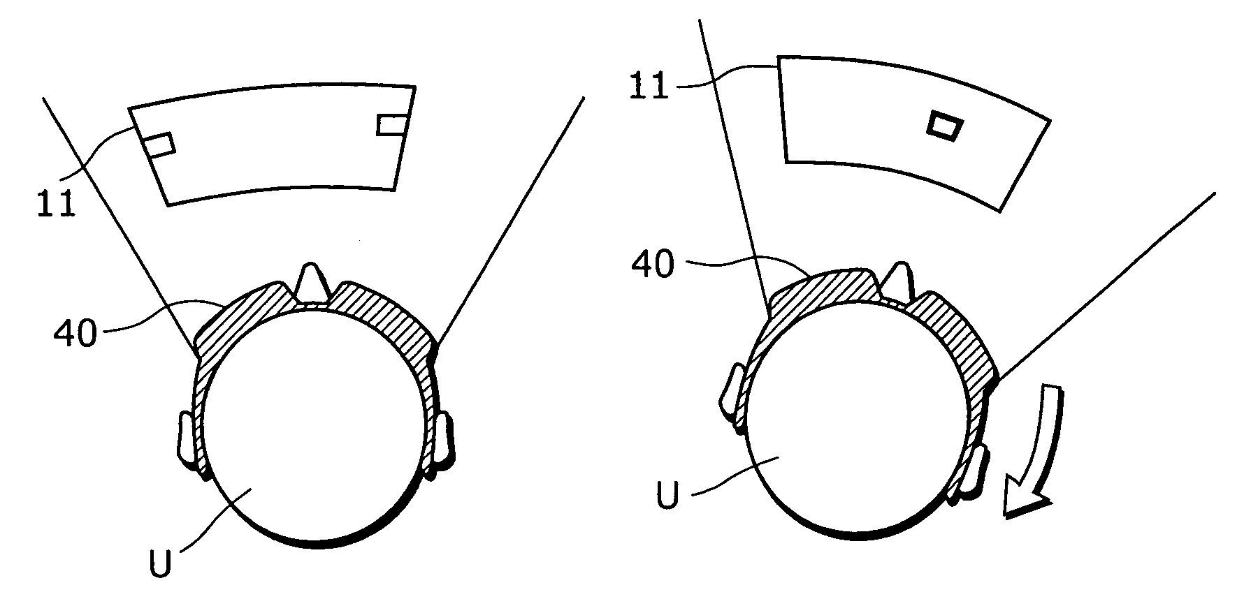
[0064]When no image data is projected, the user can see scenery around him / her routinely through the glasses. On the other hand, when image data is projected, the projected image is seen floating in the scenery.

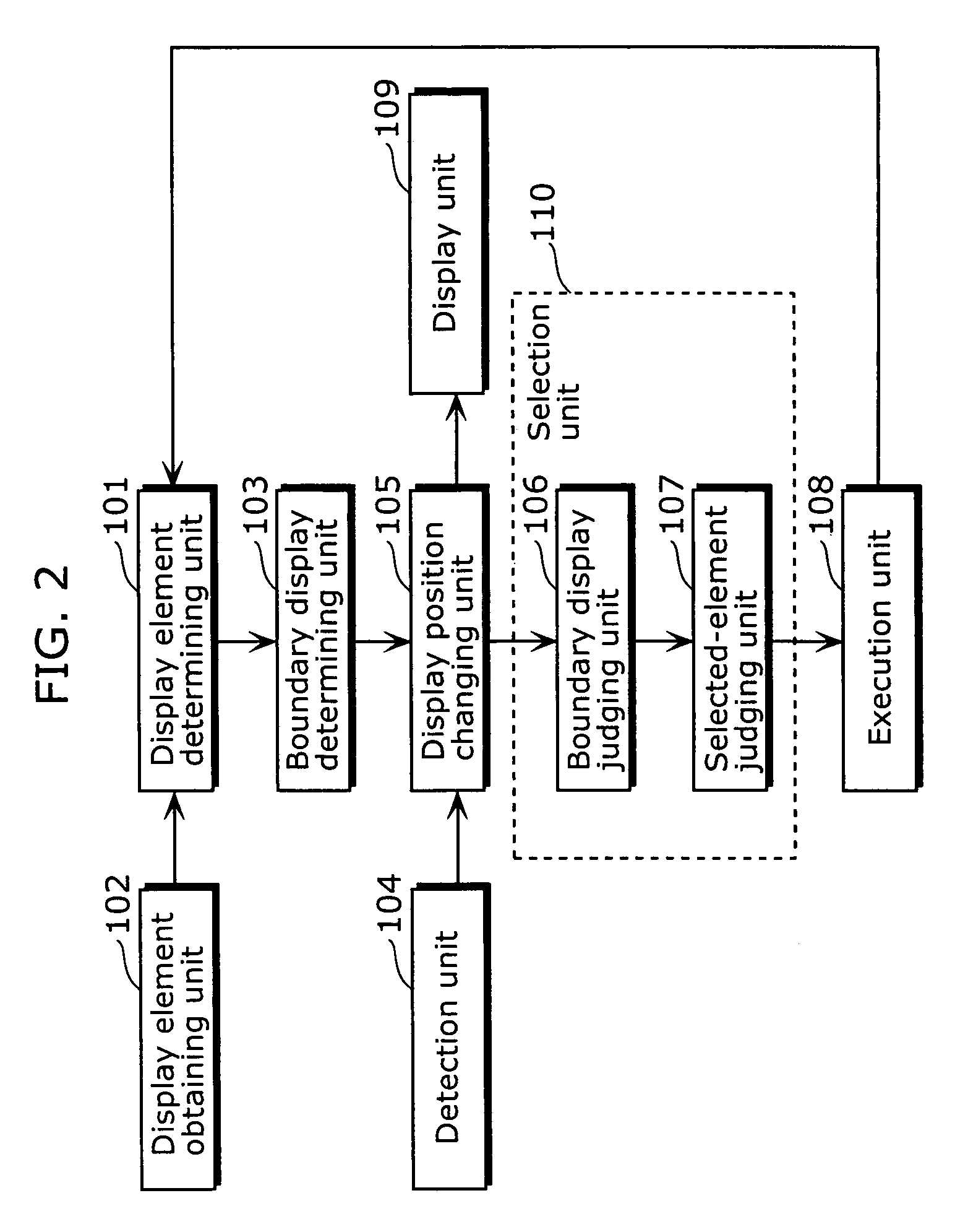
[0065]FIG. 2 is a block diagram of the display apparatus according to the first embodiment of the present invention. The display apparatus is one (e.g., HMD 40) mou...

second embodiment

[0129]Whereas in the first embodiment, an HMD has been illustrated as an example of a display apparatus, a large-screen TV will be illustrated as an example of a display apparatus in the second embodiment. The second embodiment will be described, focusing on differences from the first embodiment.

[0130]FIG. 15 is a diagram showing how a display apparatus according to the second embodiment of the present invention is used. A large-screen TV 50 is an example of the display apparatus according to the present invention. A user U watches a movie displayed on the TV 50. The TV 50 can be operated in a hands-free manner.

[0131]FIG. 16 is a block diagram of the display apparatus according to the second embodiment of the present invention. This display apparatus is a stationary display apparatus (e.g., TV 50). Functionally, it includes a display element determining unit 101, display element obtaining unit 102, boundary display determining unit 103, detection unit 104, selection unit 110, execut...


PUM


Abstract

The present invention provides a display apparatus which enables high-accuracy, hands-free operation, while adopting a low-cost configuration. The display apparatus according to the present invention includes: an obtainment unit that obtains a display element which is information to be displayed to the user; a determining unit that determines a display position of the obtained display element, at which a portion of the obtained display element can not be seen by the user; a display unit that displays the display element at the determined display position; a detection unit that detects a direction of change when an orientation of the user's head is changed; a selection unit that selects the display element to be displayed in the detected direction of change; and an execution unit that executes a predetermined process related to the selected display element.

Description

BACKGROUND OF THE INVENTION[0001](1) Field of the Invention[0002]The present invention relates to a display apparatus which displays information, and in particular to a hands-free operation technique for head-worn displays such as HMDs (head-mounted displays).[0003](2) Description of the Related Art[0004]Conventionally, hands-free operation methods which eliminate the need for manual user operation have been proposed for head-worn displays such as HMDs (head-mounted displays). Typical hands-free operation methods include a method which uses an eye camera (camera which takes images of eyeballs).[0005]For example, there is a method which estimates a user's point of regard by taking images of the user's eyeballs with an eye camera and analyzing their moving images (e.g., refer to Japanese Unexamined Patent Application Publication No. 8-286141). This method makes it possible to estimate a display element watched by the user out of multiple display elements displayed on a screen of an HM...

Claims


Application Information

Patent Timeline
Patent Type & Authority Patents(United States)
IPC IPC(8): G09G5/00
CPCG02B27/017G02B2027/0187
Inventor YAMAMOTO, KAKUYANAKAOKA, HIDEAKI
Owner PANASONIC CORP
Why Eureka
Try Eureka