Percutaneous implant

a percutaneous implant and implant technology, applied in the field of percutaneous implants, can solve the problems of scar tissue and bowel obstruction, severe surgical procedures of great discomfort for patients, skin irritation from stool, etc., to promote proper and fast identification of the guiding hole, promote strong tissue in-growth and body acceptability of the implant, and reduce the time of healing

Inactive Publication Date: 2011-05-03
OSTOMYCURE AS
View PDF26 Cites 36 Cited by
  • Summary
  • Abstract
  • Description
  • Claims
  • Application Information

AI Technical Summary

Benefits of technology

[0020]In a second aspect according to the invention, an implant is provided, which provides a stable, effective and well vascularized skin-implant junction.
[0044]The presence of the sealing material effectively prevents fluid, which flows in the accessed vessel, e.g. an intestine, from leaking in between the joined layers of various tissues and implant. The mesh further promotes strong tissue in-growth and body acceptability of the implant and reduces time of healing.

Problems solved by technology

The above-mentioned methods are drastic surgical procedures of great discomfort to the patient both before and after surgery is completed.
In summary there are several drawbacks with the above conventional methods including ulceration, incisional hernia, or bulging of the bowel through the incision, narrowing of the stoma, scar tissue and bowel obstruction, marsupialization, avulsion, skin irritation from stool that leaks under the drainage bag and necrosis.
If liquid secretion penetrates the adhesive surface, this surface will loosen to a certain extent, resulting in leakage from the pouch and the release of an unpleasant smell.
Another problem with ostomies is that the site where the intestine passes the abdominal wall is weak and susceptible to herniation.
Hernias result in blockage of the stoma and relief surgery is urgently required.
The barrel surrounds and supports the stoma, however the rigid wall of the implant critically restricts the peristaltic movements.
Use of this device involves a high risk of total or partial rupture between tissue and implant, e.g. in case of high back pressure resulting from constipation.
Urine or stool may leak and cause inflammation and peritonitis.

Method used


Image

  • Percutaneous implant
  • Percutaneous implant
  • Percutaneous implant

Examples


Embodiment Construction

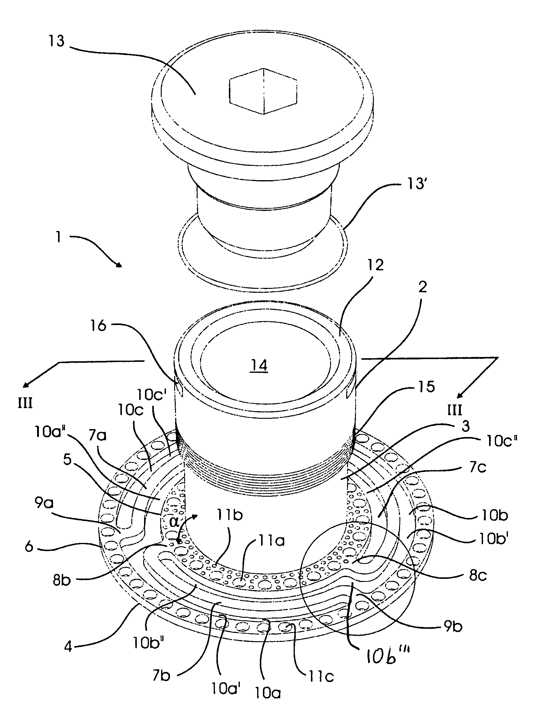
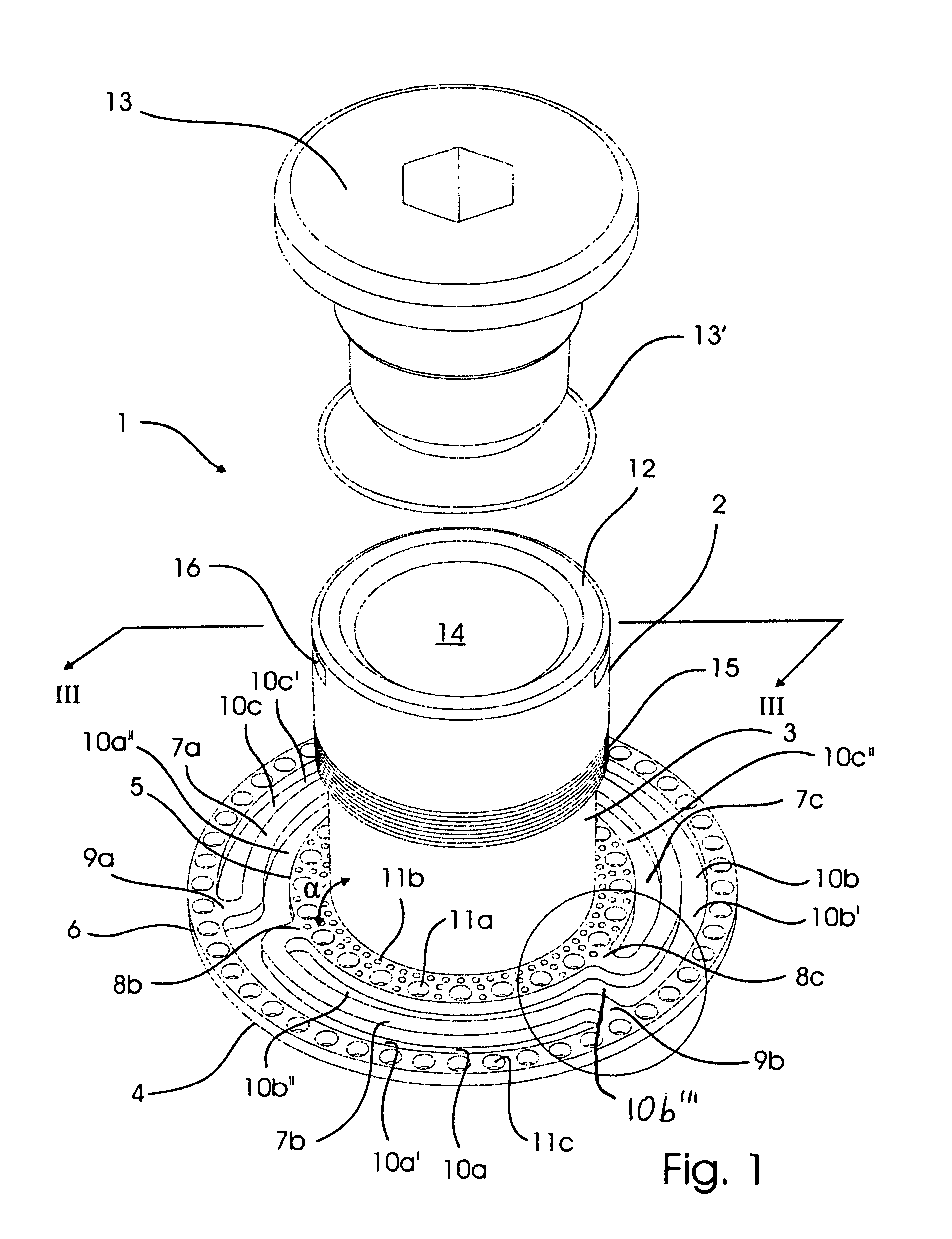
[0058]The implant shown in FIGS. 1 and 2 is in its entirety designated with reference number 1. The implant 1 is only by way of an example shown in the drawing implanted in relation to the ileum, however the use with any other vessel is intended within the scope of the present invention.

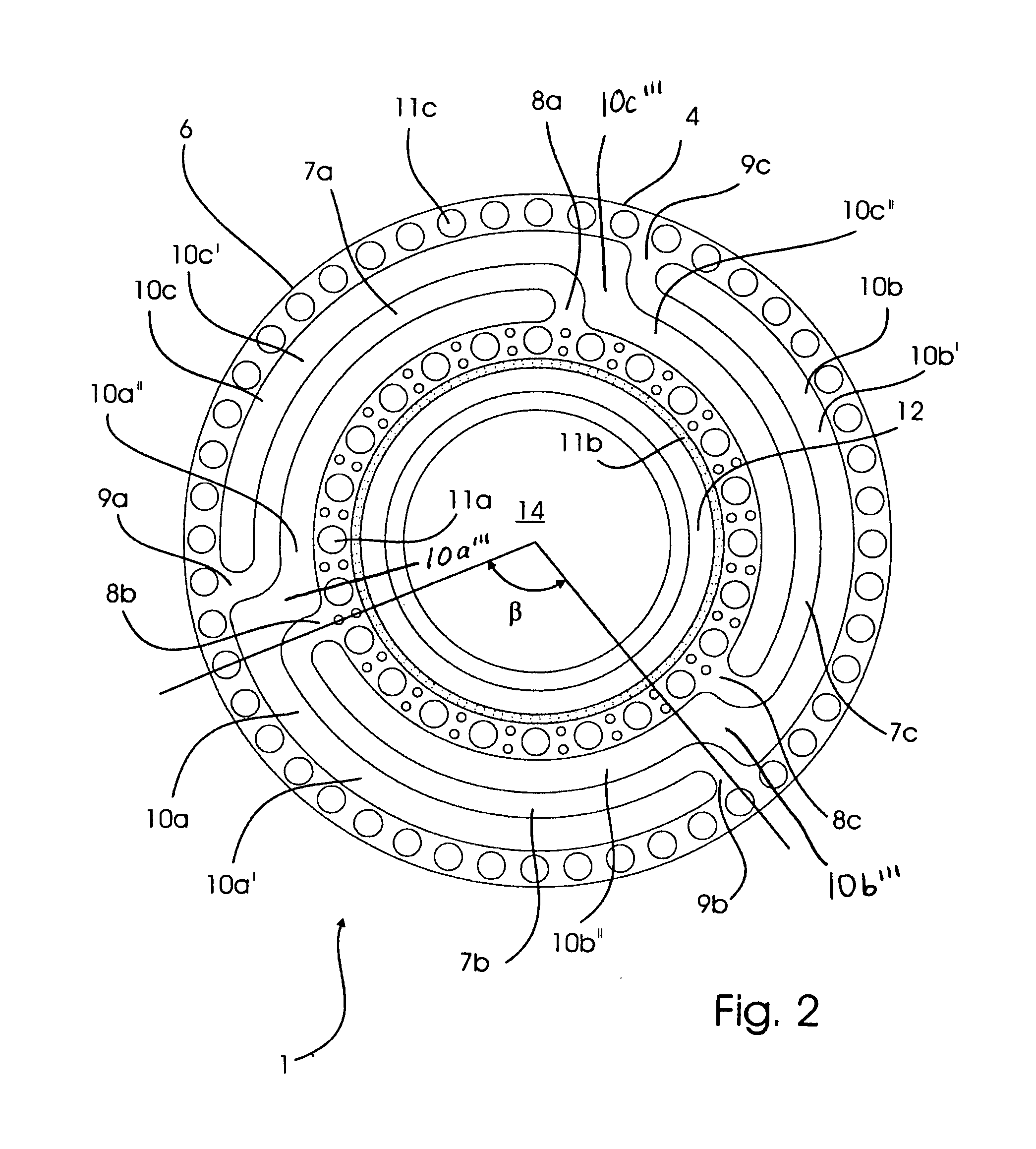
[0059]FIG. 1 shows an implant 1 with an axial exterior section 2, an axial interior section 3, from which an anchoring section 4 extends radially in an angle α of approximately 90°. The anchoring section 4 consists of an inner anchoring ring 5, an outer anchoring ring 6 concentric with the inner anchoring ring 5 and three elongated connection members 7a,7b,7c for connecting the inner anchoring ring 5 with the outer anchoring ring 6. As seen best in FIG. 2 the connection member 7b is connected at a substantially right angle to the inner anchoring ring 5 at a first connection point 8b, and at a substantially right angle to the outer connection ring 6 at a second connection point 9b. In a similar manner...


PUM


Abstract

A percutaneous implant serves for implantation into an animal or a human body. The implant is of the kind that has an anchoring section, extending radially from a distal end of an interior section. The anchoring section comprises an inner anchoring ring extending from or integral with the interior section, an outer anchoring ring, and at least one connection member for connecting the inner anchoring ring with the outer anchoring ring. Since a first connection point between a first end of the at least one connection member and the inner anchoring ring is angularly offset from a second connection point between a second end of the connection member and the outer anchoring ring, the anchoring section constitutes a resilient spring means, which adapts to the movements of the body. The implant is especially designed for use without externalization of the vessel to be brought into communication with the exterior.

Description

[0001]This application claims the benefit of U.S. provisional application 60 / 615,576 filed Oct. 5, 2004.BACKGROUND[0002]The invention relates to a percutaneous implant for implantation into an animal or a human body.[0003]A method for implantation of the implant according to the present invention into an animal or a human body is also described together with preferred uses.[0004]The implant is of the kind comprising an axial interior section for fixation inside the body, an axial exterior section in communication with the interior section, said axial exterior section extending outwards from the body with a free end, which serves for mounting of a detachable device, the distal end of the interior section opposite the exterior section being provided with an subcutaneous anchoring section, extending radially from the distal end of the interior section.[0005]Many diseases such as e.g., Crohn's disease, ulcerative colitis, intestinal cancer and adenomatous polyposis or bladder cancer req...

Claims


Application Information

Patent Timeline
Patent Type & Authority Patents(United States)
IPC IPC(8): A61F5/44A61M5/32
CPCA61M25/02A61M2025/0286A61M2025/0293
Inventor JOHANSSON, MARTINAXELSSON, ROBERTJOHNSSON, ANETTEEDWIN, BJORNFOSSE, ERIK
Owner OSTOMYCURE AS
Why Eureka
Try Eureka