Marine vehicle seat mount

a vehicle seat and mount technology, applied in the field of vehicle seats, can solve the problems of operator discomfort, large difficulty in removing the bolts, and inability to maintain stability and precision in operation

Active Publication Date: 2011-05-10
BRUNSWICK CORPORATION
View PDF22 Cites 8 Cited by
  • Summary
  • Abstract
  • Description
  • Claims
  • Application Information

AI Technical Summary

Problems solved by technology

With a perimeter flange, however, stability and precision in operation may be an issue.
In particular, any movement of the vehicle seat may result in operator discomfort.
In particular, the bolts are oftentimes directly exposed to the elements, including water, which may result in the oxidation of the bolts and result in great difficulty in removing the bolts.
Additionally, the exposed bolts may be unsightly as they may appear unfinished.

Method used


Image

  • Marine vehicle seat mount
  • Marine vehicle seat mount
  • Marine vehicle seat mount

Examples


Embodiment Construction

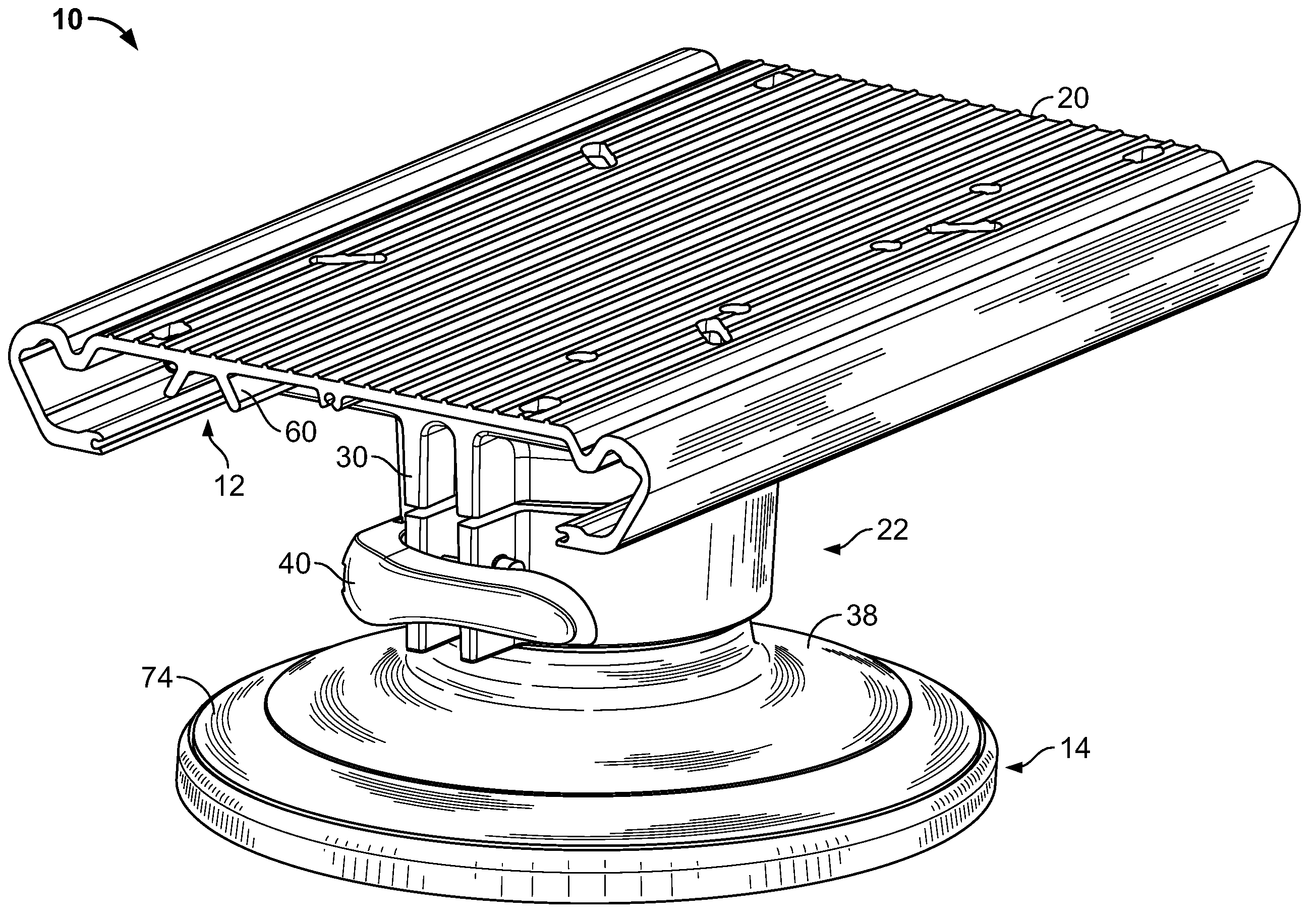
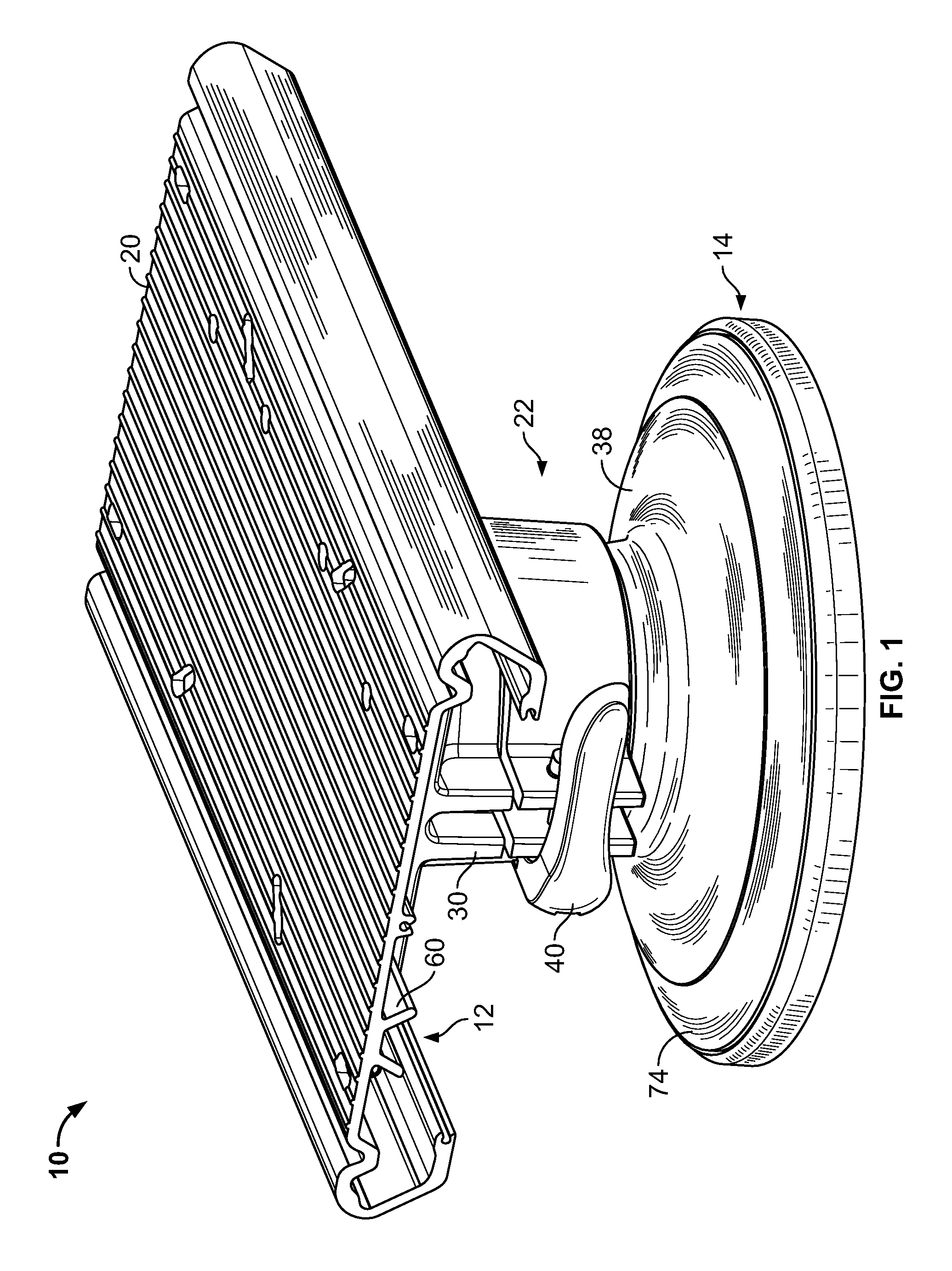
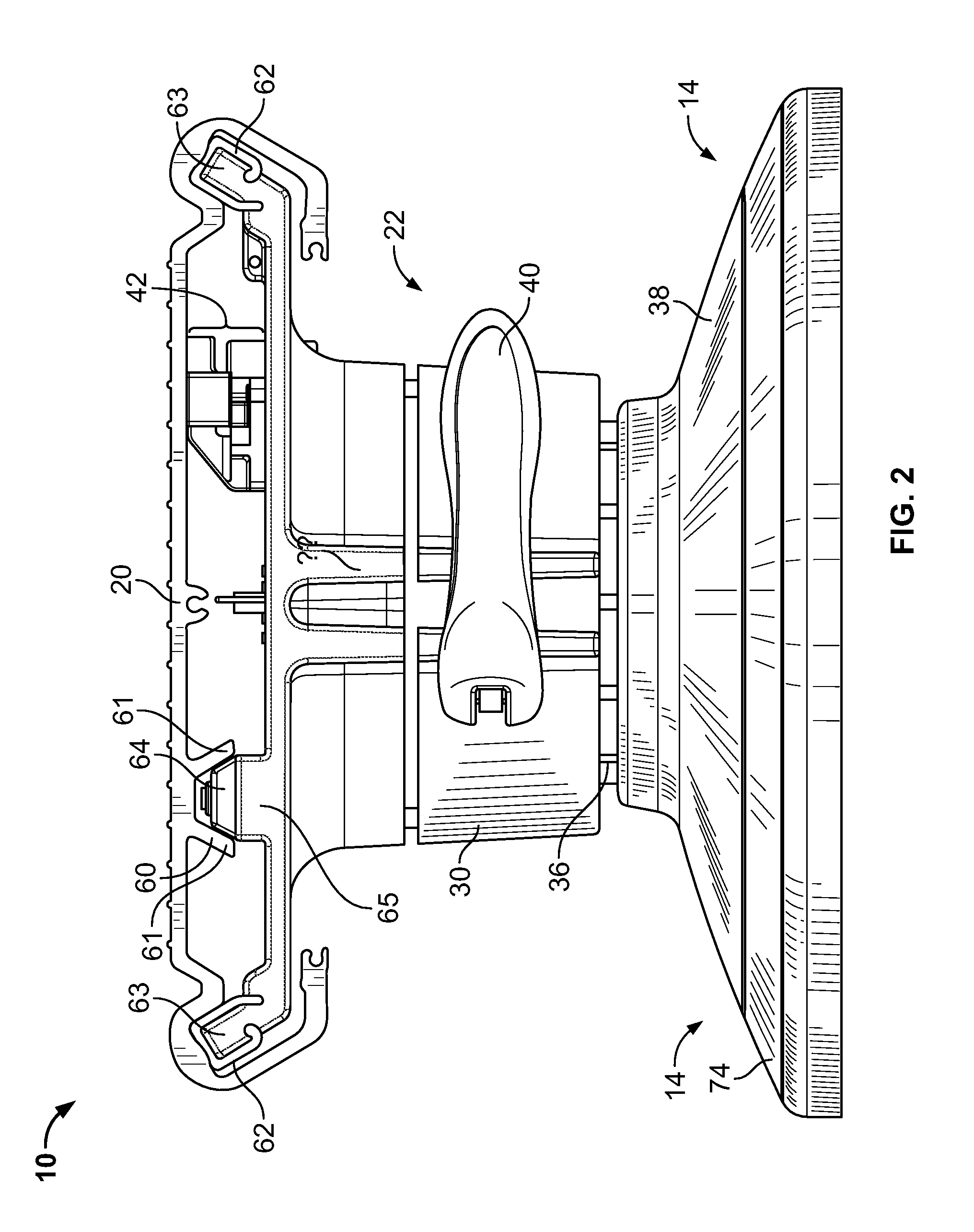
[0016]FIGS. 1-3 depict an example vehicle seat mount assembly 10 including an example v-shaped slider glide 12 and an example base bell trim cover 14 described herein. Referring to FIGS. 1-3, a vehicle seat (not shown) is coupled or mounted to the example vehicle seat mount assembly 10 via a pedestal slider plate 20. The slider plate 20 is, in turn, slidably coupled to a support stand 22, which, in turn, may be coupled or fixed to a floor surface of a vehicle (not shown). The example support stand 22 generally includes a seat mount 30, a seat mount bushing 32, a tube top bushing 34, a tube pedestal 36, and a base bell 38.

[0017]The vehicle seat mount assembly 10 may be configured for use in any desired type of vehicle including, for example, a boat, a car, a recreational vehicle, heavy equipment, etc. Additionally, the vehicle seat may be configured (e.g., sized, shaped, utilizes materials, etc.) to suit the particular vehicle in which the example vehicle seat mount assembly 10 is to...


PUM


Abstract

A seat slider assembly is disclosed. The slider seat includes a seat mount and a first slider guide extending along at least a portion of the perimeter of the seat mount. A second slider guide extends from the surface of the seat mount at a position distally located from the perimeter of the seat mount. A slider plate to which a vehicle seat can be mounted includes a first channel for slidably engaging the first slider guide and a second channel for slidably engaging the second slider guide such that the slider plate is slidable between a first position and a second position relative to the seat mount. A locking lever is movably coupled to the slider plate and includes a locking structure to prevent the slider plate from moving relative to the seat mount. A control member operatively coupled to the locking lever to cause the locking lever to move toward an unlocked position wherein the locking structure allows the slider plate to move relative to the seat mount. In some examples, a trim piece is adapted to at least partially cover fasteners mounting the assembly to a vehicle support surface.

Description

CROSS REFERENCE TO RELATED APPLICATION[0001]This application is a non-provisional application claiming priority from U.S. Provisional Application Ser. No. 60 / 911,004, filed Apr. 10, 2007, and incorporated herein by reference in its entirety.FIELD OF THE DISCLOSURE[0002]The present disclosure relates generally to vehicle seats and more particularly to a marine vehicle seat mount.BACKGROUND OF RELATED ART[0003]Many vehicle seats such as those used in boats include a swiveling and / or sliding seat mount coupled to a post and base assembly in the boat. A swiveling or sliding seat mount enables a seated vehicle occupant to rotate and / or slide their seat to a desired position, which typically occurs when the vehicle is relatively stationary to enable, for example, an operator of the vehicle (e.g., a driver) to adjust the position of their seat for use of vehicle controls, comfort, safety, etc.[0004]Sliding seat assemblies have included a slider plate slidably coupled to a base mount. The s...

Claims


Application Information

Patent Timeline
Patent Type & Authority Patents(United States)
IPC IPC(8): B63B17/00
CPCB63B29/06
Inventor DRAGHICI, ADRIANDOWNEY, KEVIN
Owner BRUNSWICK CORPORATION
Why Eureka
Try Eureka