Slipform paving machine with adjustable length paving kit

a technology of slipform paving machine and paving kit, which is applied in the direction of roads, roads, construction, etc., can solve the problems of reducing the time available for actual paving, increasing the complexity and difficulty of changing the width of the tractor frame, and tedious work to put it all together before the machine becomes operabl

Active Publication Date: 2011-05-31
GUNTERT & ZIMMERMAN CONSTR DIV
View PDF11 Cites 31 Cited by
  • Summary
  • Abstract
  • Description
  • Claims
  • Application Information

AI Technical Summary

Benefits of technology

[0009]It is a principal object of the present invention to streamline and speed up changing the width of the paving kit from one dimension to another for sequentially laying concrete strips of correspondingly different widths.
[0015]The paving kit of the present invention further includes a metering gate located forward of the paving kit for striking off the freshly supplied concrete and for assistance in maintaining a desirable constant head height over the poker vibrators, a vibrator arrangement between the metering gate and the paving kit for vibrating and temporarily liquefying the supplied concrete prior to finishing it, and a trailing finishing pan located on an aft side of the paving machine for further finishing the upwardly exposed concrete surface adjacent the lateral sides of the concrete. The components of these subsystems of the paving machine, which require adjustments when the lengths of the terminal kits are changed, are, like the components of the terminal kit, configured and arranged so that they too can be changed by a single person using only simple hand tools and without requiring a disassembly of the paving kit and / or lifting equipment for handling heavy components.

Problems solved by technology

Adding one or more fixed frame extensions significantly increases the complexity and difficulty of changing the width of the tractor frame.
In the past, this was a major task that required heavy equipment, such as a crane, a partial disassembly of the paving machine, and tedious work to put it all together before the machine becomes operable again.
This is a task that typically takes between eight to twelve hours, requires at least two persons, involves costly equipment, requires hydraulic lines and electrical cords to be disconnected and then reconnected, and unproductively idles the machine during the width change process, all of which is undesirable because it increases costs and reduces the time available for actually paving.

Method used


Image

  • Slipform paving machine with adjustable length paving kit
  • Slipform paving machine with adjustable length paving kit
  • Slipform paving machine with adjustable length paving kit

Examples


Embodiment Construction

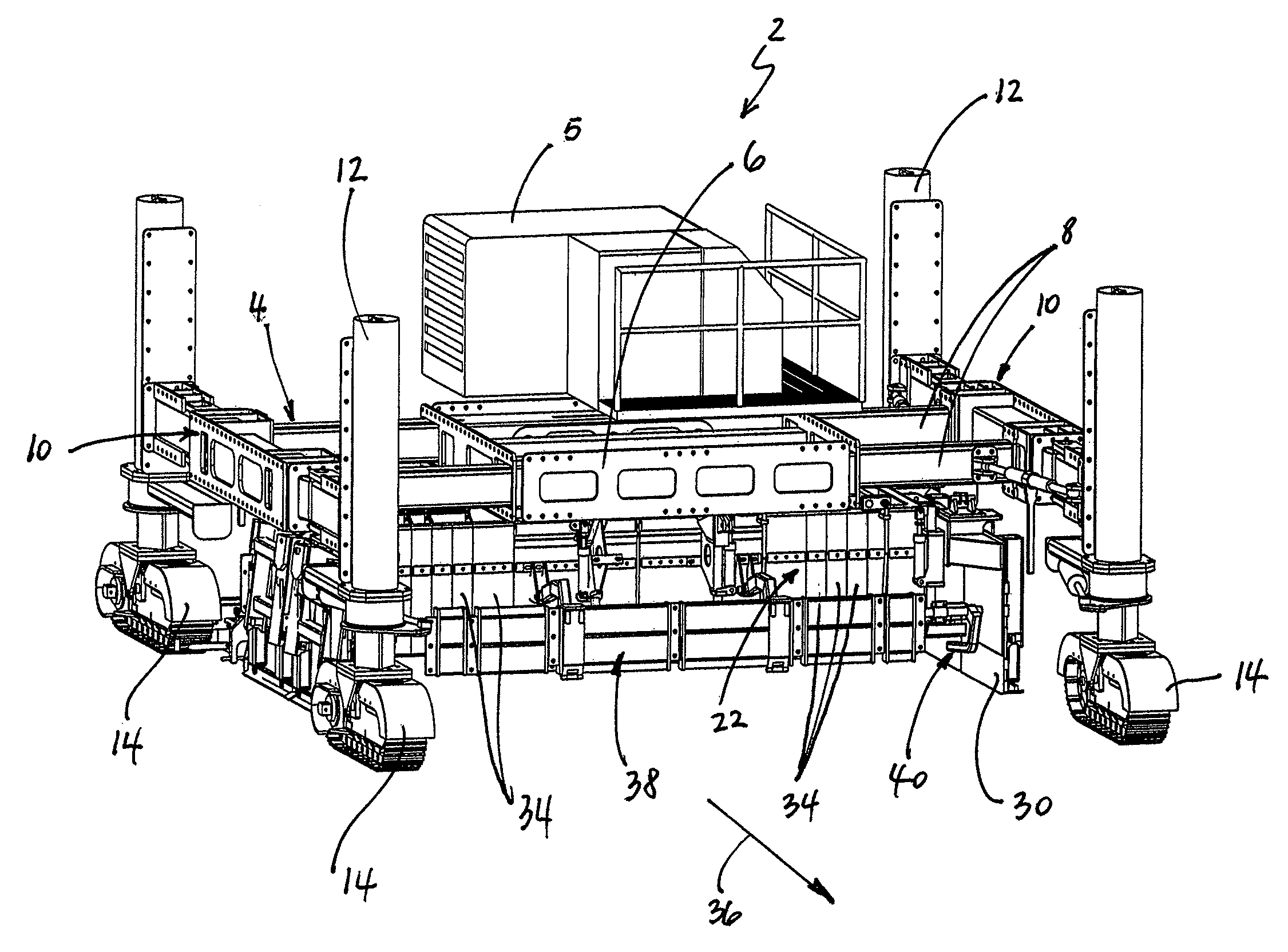
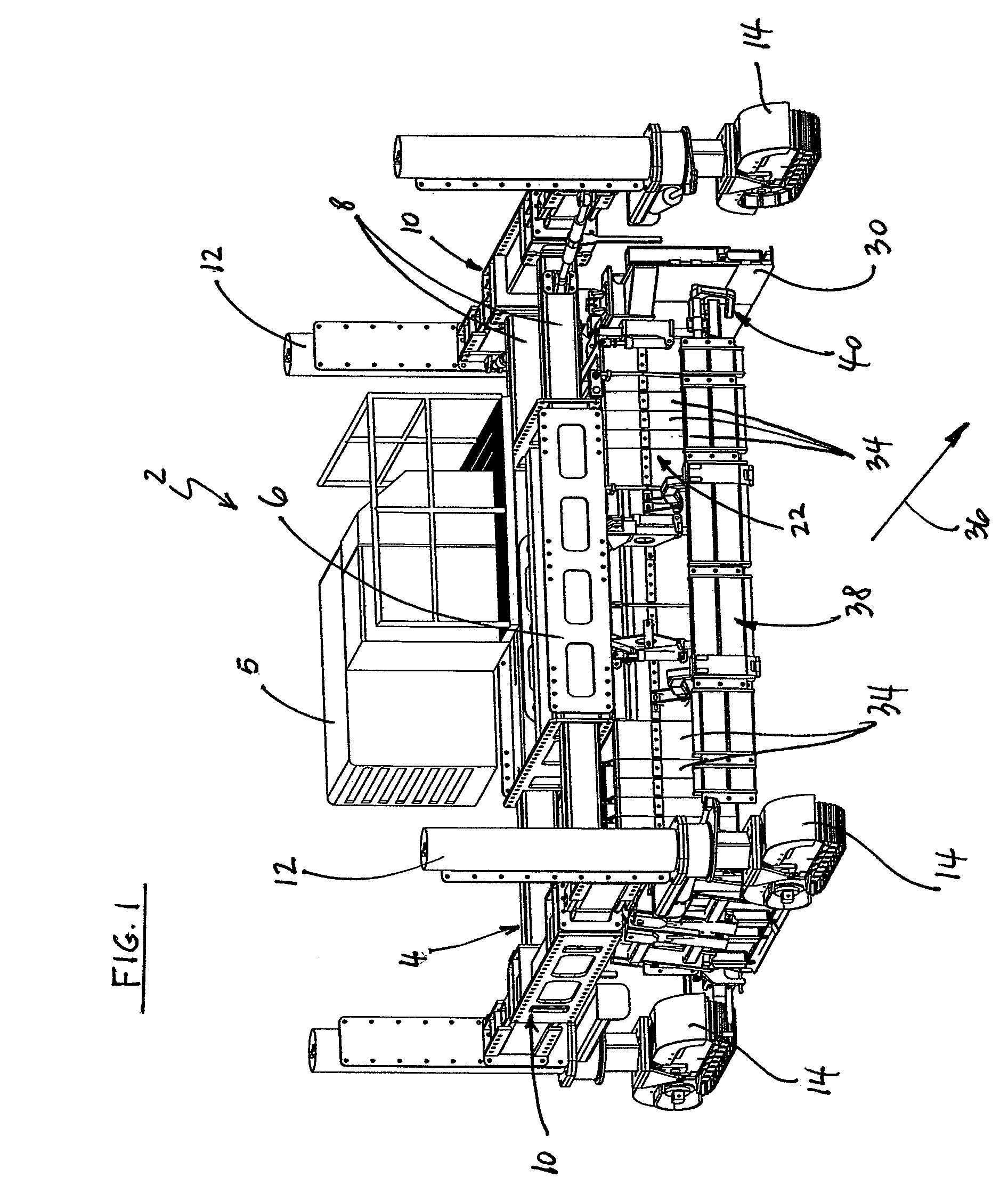
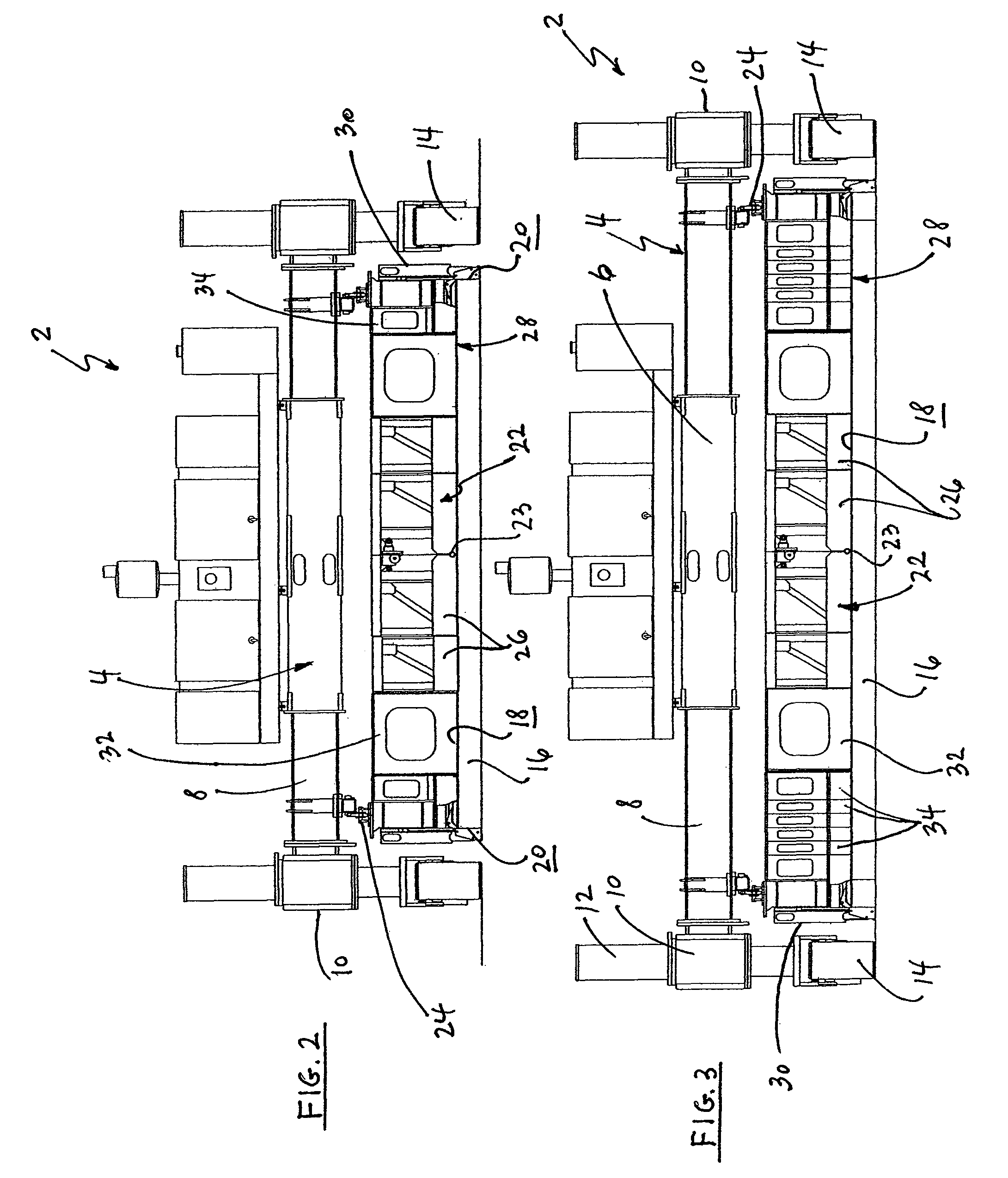
[0029]Referring initially to FIGS. 1-3, a slipform paving machine 2 has a main tractor frame 4 defined by a central module or platform 6 that carries the diesel engine powered power unit 5 of the paving machine and from which telescoping support beams 8 extend outwardly in a lateral direction. Bolsters 10 are secured to the respective outboard ends of the support beams. Upright jacking columns 12 are mounted at front and aft ends of the bolsters, and crawlers 14 are conventionally secured to the lower ends of the jacking columns. The jacking columns enable the raising and lowering of the paving machine. The crawlers are mounted and rotatable relative to the lower ends of the jacking columns. They support the entire machine and move it over the ground.

[0030]In use, the respective bolsters are moved in the lateral direction so that the machine frame, including the crawlers, extends over and clears a strip of concrete 16 being laid by the machine. When finished, the strip of concrete d...


PUM


Abstract

A concrete paving machine which has a main frame and two hydraulic jacking columns at each end of the frame for raising and lowering the machine frame. Crawlers attached to the jacking columns move the paving machine in the travel direction. A paving kit is secured to the main frame and has a rigid center portion. Each terminal kit has an end frame secured to the center portion, an adjustable length support structure between the end frame and the slipform, and a hydraulic actuator. Spacers are interposed between the end frame and the slipform. A finishing pan is provided to finish the concrete surface. All replaceable components of the terminal are constructed and arranged so that they can be manually exchanged be one or two persons without removing the paving kit from the main frame and without needing the help of lifting equipment.

Description

BACKGROUND OF THE INVENTION[0001]The present invention concerns concrete slipform paving machines that are made up by a propelling unit or tractor from which a paving kit is suspended with which a layer of concrete is shaped and finished as the propelling unit travels along a road or airfield alignment. The paving kit is configured so that its length can be manually varied in the field in an exceedingly short period of time requiring only simple hand tools such as wrenches, pry bars and hammers.[0002]The tractor of concrete slipform paver has a rectilinear frame which straddles the concrete roadway or airfield pavement section that is being paved. The frame is propelled and supported on either end by crawler tracks mounted on side bolsters. These side bolsters each have two hydraulic supporting jacking columns that allow the tractor frame elevation to be manually or automatically varied relative to the ground. The frame, and in particular a center module thereof, supports a diesel e...

Claims


Application Information

Patent Timeline
Patent Type & Authority Patents(United States)
IPC IPC(8): E01C19/12
CPCE01C19/42E01C2301/18
Inventor GUNTERT, JR., RONALD M.FRANCIS, RICHARD W.
Owner GUNTERT & ZIMMERMAN CONSTR DIV
Why Eureka
Try Eureka