
Flexible knitting pin

a knitting pin and flexible technology, applied in the field of flexible knitting pins, can solve problems such as obstructed knitting pin function

Active Publication Date: 2011-06-07
DEVAGNANAM THEOPHILUS ARPUTHARAJ
View PDF24 Cites 23 Cited by
  • Summary
  • Abstract
  • Description
  • Claims
  • Application Information

AI Technical Summary

Problems solved by technology

This results in obstructed functioning of the knitting pin.

Method used


Image

  • Flexible knitting pin
  • Flexible knitting pin
  • Flexible knitting pin

Examples


Embodiment Construction

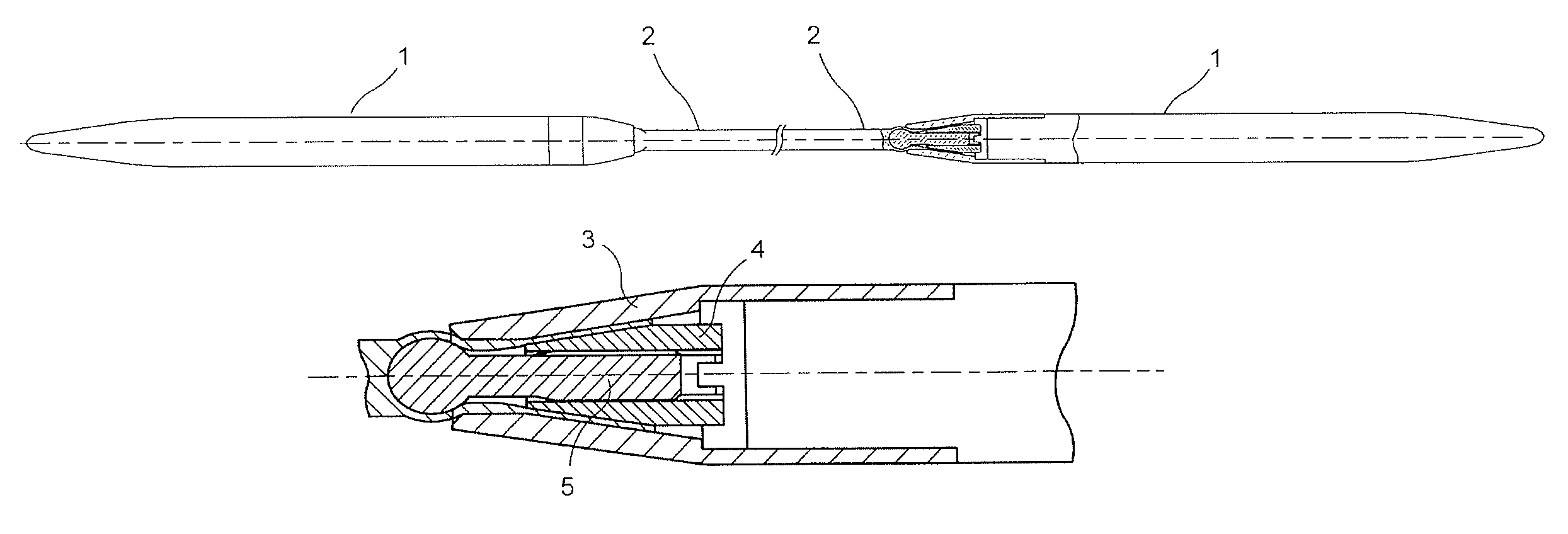
[0006]The present invention relates to a flexible knitting pin, specifically, circular knitting pin made from any material which enables smoother movement of stitches compared to the prior art and is easier to use. Also, the method of realizing this invention is relatively simple while maintaining the same functionality.

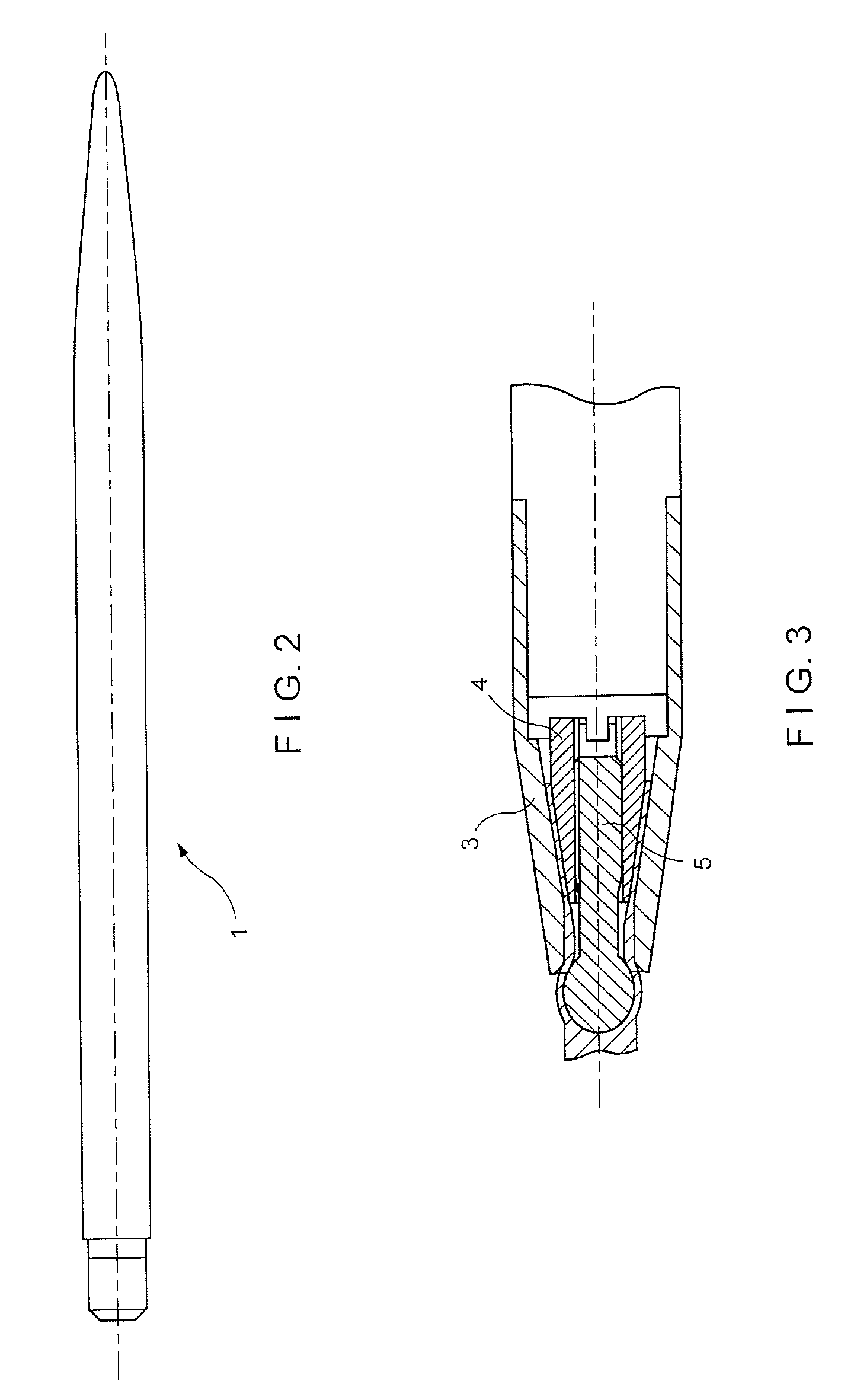
[0007]The knitting needle consists of two stiff shanks which are pointed at one end and suitably machined for attachment at the other. These shanks are then connected to each other using a flexible tube.

[0008]Thus the product consists of two stiff shanks, suitably pointed at one end each for knitting and connected from the other end using a flexible hollow tube. The joint between the stiff shanks and the flexible hollow connecting tube consists of a metal sphere, hemisphere or cone positioned inside the hollow connecting tube at a fixed position up against the end of the stiff shank. The joint between the stiff shanks and the hollow flexible connecting tube is extrem...


PUM

PropertyMeasurementUnit
flexibleaaaaaaaaaa
diameteraaaaaaaaaa
inner diameteraaaaaaaaaa

Abstract

A flexible knitting pin consisting of two relatively stiff shanks (1) pointed one end each, wherein said shanks (1) are connected with each other by the other end with a flexible hollow connecting material (2) comprising a joint; said joint between the stiff shanks (1) characterized in that it comprises a flexible hollow connecting material.

Description

FIELD OF THE INVENTION[0001]The present invention relates to flexible knitting pin, specifically circular knitting pin made from any material. Accordingly, a method to realize this invention is also provided.BACKGROUND OF THE INVENTION[0002]Conventional knitting pins are known to have metal shanks comprising of a nylon monofilament. The step formed at the junction, usually prepared from nylon monofilament is not smooth and therefore, the step catches the wool. This results in obstructed functioning of the knitting pin.[0003]British patent GB876144 describes circular knitting pins of two relatively stiff metal end parts joined by a flexible connection made from a polymer plastics material. The flexible connecting tube is joined to the end parts by making axial bores in the undrawn end portions of the flexible connection made from a length of moulded or extruded plastic material, inserting the surface roughened spigots into the axial bores of the flexible connection while supplying su...

Claims


Application Information

Patent Timeline
Patent Type & Authority Patents(United States)
IPC IPC(8): D04B35/02
CPCD04B3/02Y10T29/49826
Inventor DEVAGNANAM, THEOPHILUS ARPUTHARAJ
Owner DEVAGNANAM THEOPHILUS ARPUTHARAJ
Learn More