

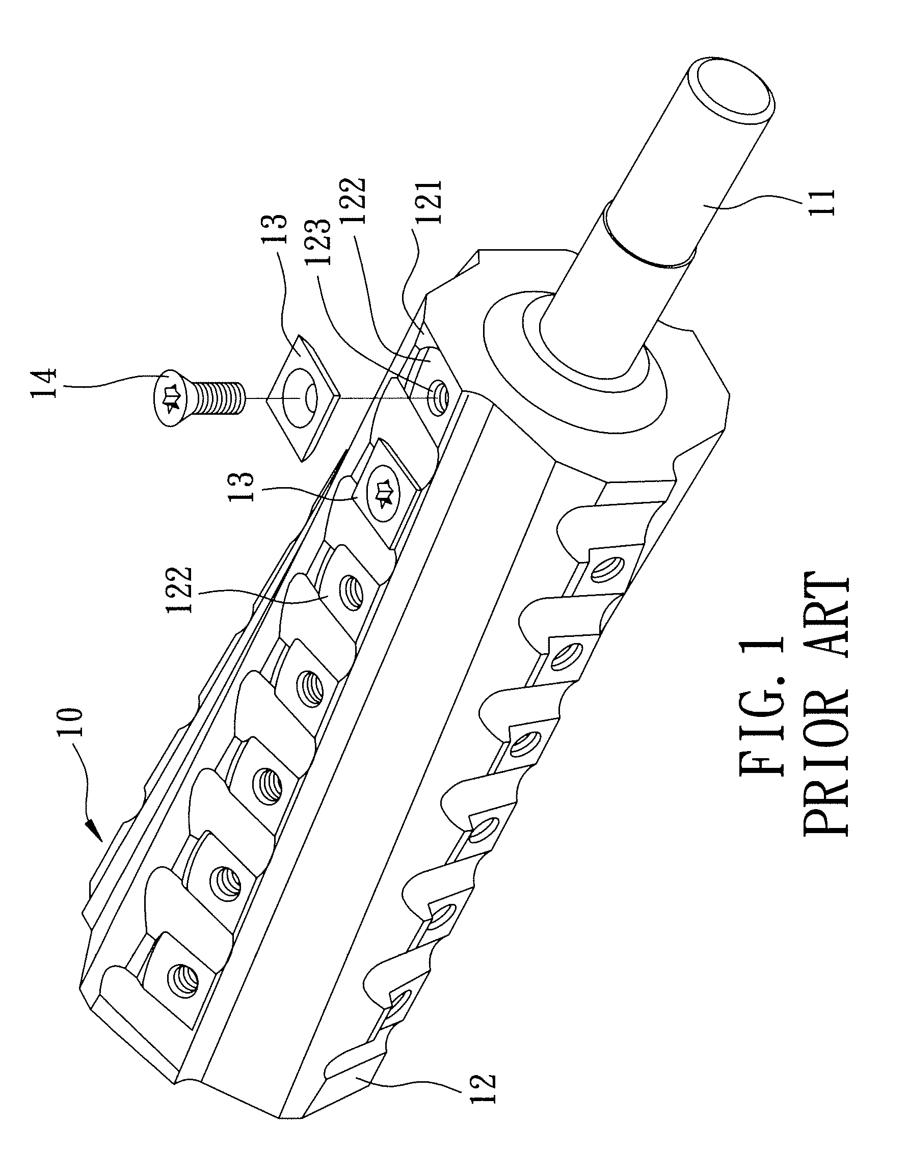
Cutter head assembly for a wood planing machine
a wood planing machine and cutter head technology, applied in the direction of special profiling/shaping machines, flat surfacing machines, profiling/shaping machines, etc., can solve the problems of difficult fabrication of the shaft b>12/b>, cost and time consumption, and achieve the effect of convenient and less costly fabrication
- Summary
- Abstract
- Description
- Claims
- Application Information
AI Technical Summary
Benefits of technology
Problems solved by technology
Method used
Image

Examples
Embodiment Construction
[0019]Before the present invention is described in greater detail, it should be noted that same reference numerals have been used to denote like elements throughout the specification.
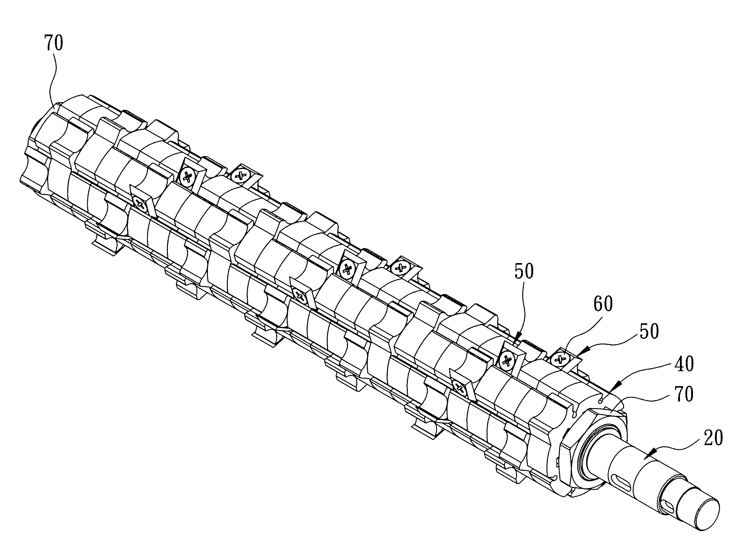
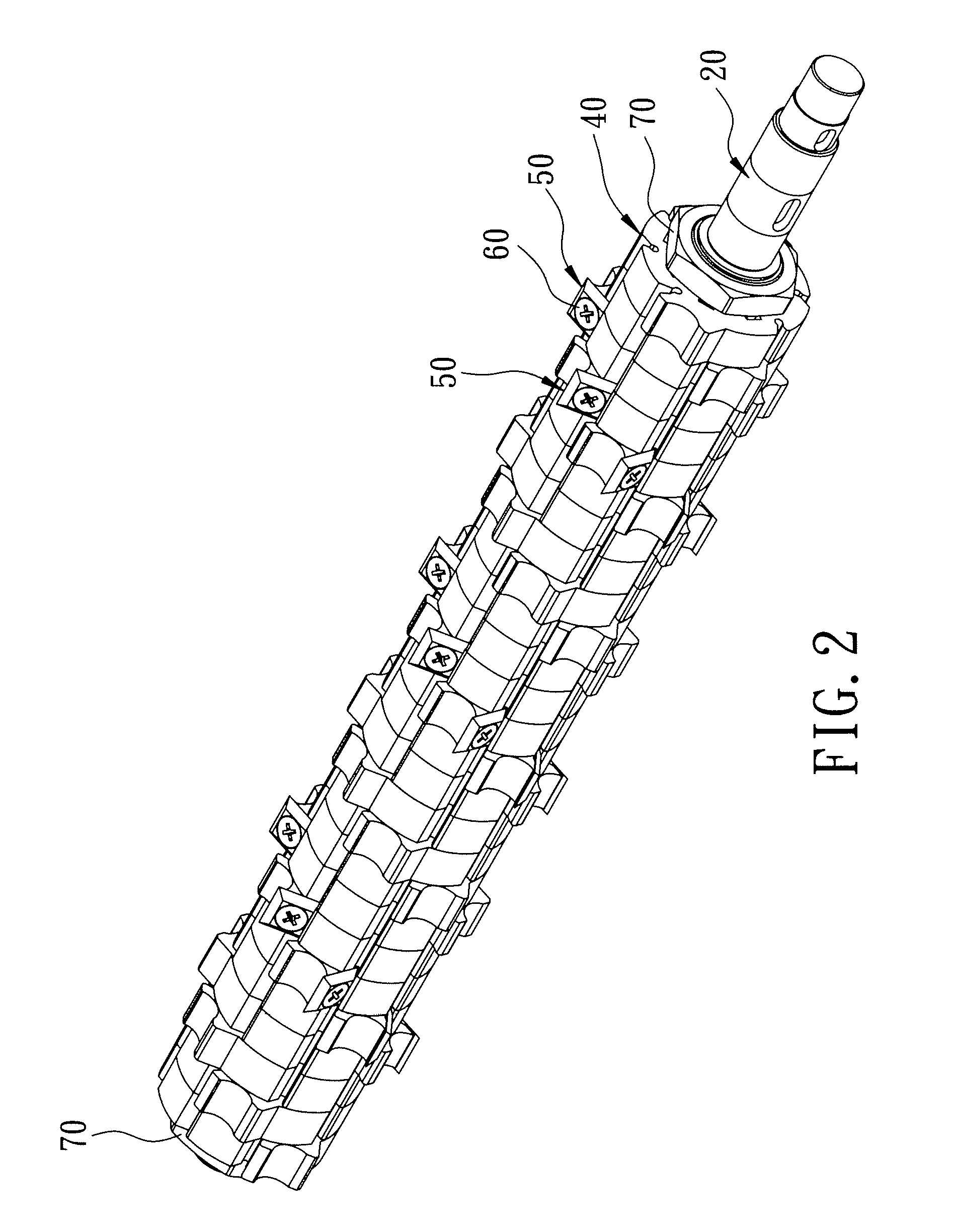
[0020]Referring to FIGS. 2 to 5, the first preferred embodiment of a cutter head assembly according to the present invention is adapted for use with a wood planing machine (not shown), and is shown to comprise a shaft 20, a plurality of cutter-mounting sleeve modules 40, a plurality of cutter modules 50, an angularly-variable positioning mechanism, and two fasteners 70.
[0021]The shaft 20 is elongated along an axis (I) in an axial direction, and has two ends 23 opposite to each other along the axis (I), and a mount segment 21 interposed between the ends 23.
[0022]Each of the cutter-mounting sleeve modules 40 (only one is shown in FIG. 4) has outer and inner wall surfaces 42,41 opposite to each other in radial directions. The outer wall surface 42 defines a slot 44 which extends towards the inner wall surf...
PUM
 Abstract
Description
Claims
Application Information