Axial gap type rotating machine
a gap type, rotating machine technology, applied in the direction of magnetic circuit rotating parts, magnetic circuit shape/form/construction, instruments, etc., can solve the problems of reducing magnetic efficiency, generating cogging torque and loss torque, and a slight wind that fails to produce voltage, etc., to achieve the effect of not reducing the magnetic flux
- Summary
- Abstract
- Description
- Claims
- Application Information
AI Technical Summary
Benefits of technology
Problems solved by technology
Method used
Image
Examples
examples
[0072]Embodiments will be described in detail below. The present invention is not limited by the embodiments below. Although an Nd2—Fe14—B type permanent magnet will be described, the present invention is not limited to Nd—Fe—B type magnets.
production example
Production of a Permanent Magnet
[0073]A permanent magnet was fabricated by the following process. Nd, Fe, Co, M (M is Al, Si, Cu) each having a purity of 99.7% by mass and B having a purity of 99.5% by mass were used and an ingot was fabricated by melting and casting in a vacuum melting furnace. This ingot was coarsely crushed by a jaw crusher and further fine powder having an average particle diameter of 3.5 μm was obtained by jet mill crushing in a nitrogen gas stream. This fine powder was filled in a die and formed under a forming pressure of 1.0 t / cm2 in a magnetic field of 12 kG by transverse magnetic field press. This compact was subjected to sintering for an hour at 1090° C. in Ar gas, and subsequently subjected to heat treatment for an hour at 580° C. The sintered compact after the heat treatment was in a shape of a rectangular parallelepiped block. This block was subjected to grinding processing by a grindstone to obtain a D-shaped permanent magnet. The properties of the pr...
working example 1
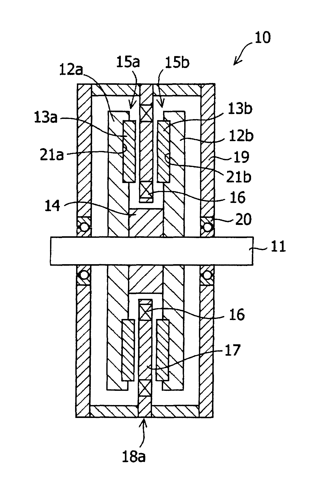
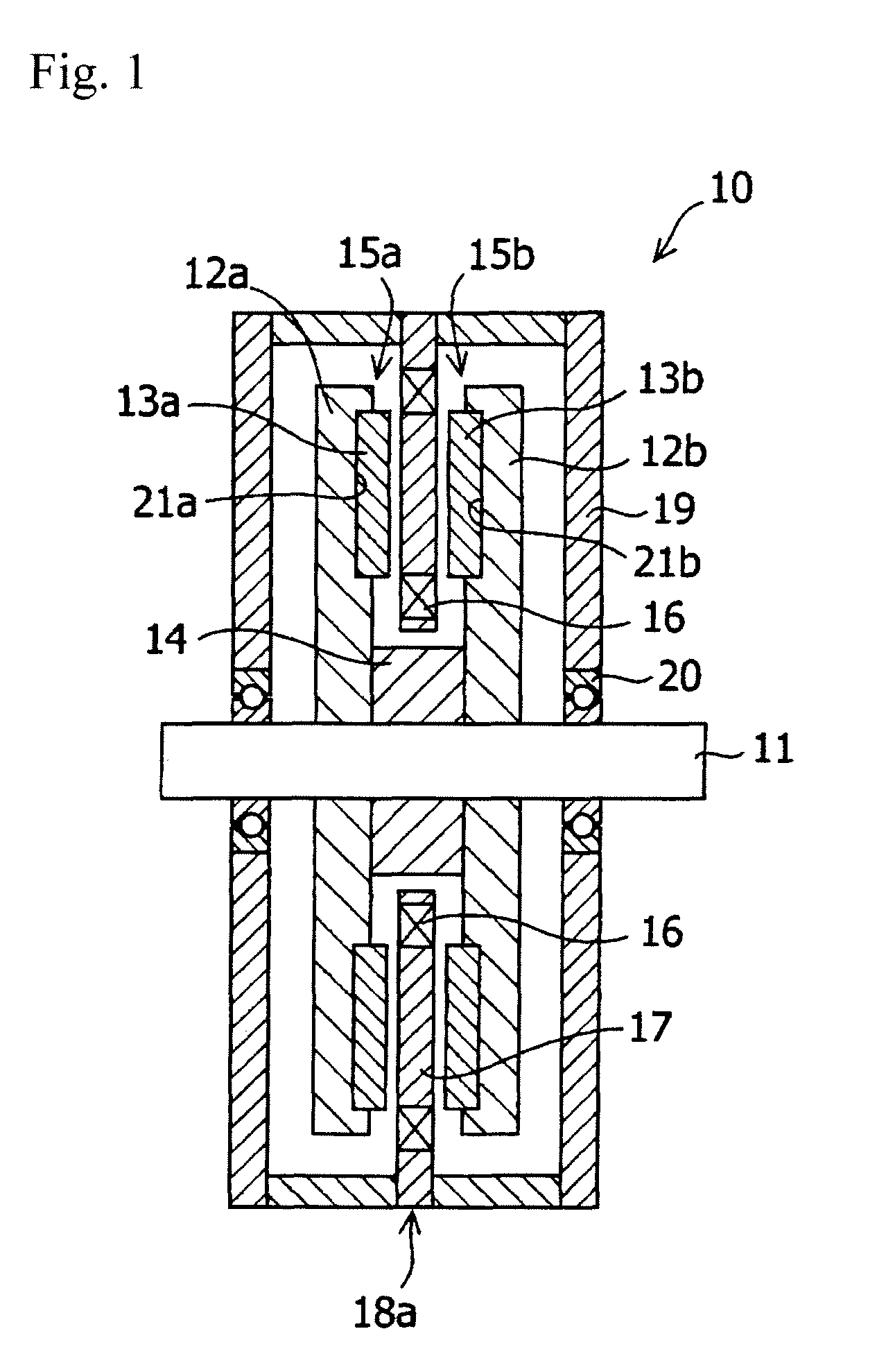
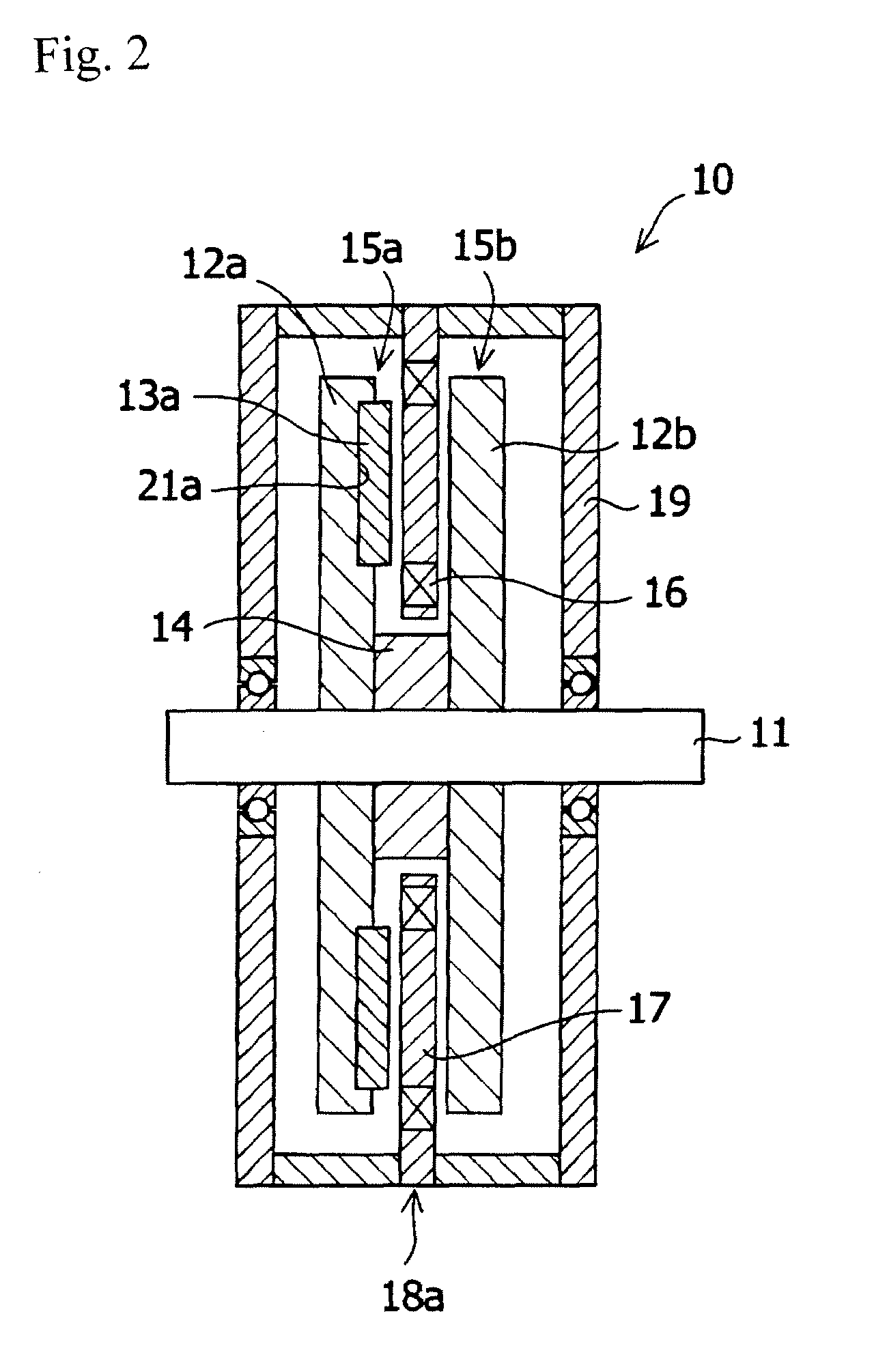
[0079]The configuration of the axial gap type rotating machine of the Embodiment 1 is shown in FIG. 1. The materials and the dimensions were the same as Comparative Example 1 except that the rotor had a structure in which the magnets were disposed at the rotor yoke. As shown in FIG. 5, sixteen magnets 13 were inserted in sixteen concave portions 21 of a rotor yoke 12 formed concentrically in spaced relation to each other, with the pole surfaces being alternately an N pole and an S pole. As shown in FIG. 6, the thickness T1 of the permanent magnet was 4 mm and the fitted length T2 was 2 mm. The magnets 13 and the rotor yoke 12 were bonded by applying elastic adhesive (EP001, manufactured by Cemedine Co., Ltd.) to the side surfaces and the bottom surfaces of the concave portions.
[0080]Next, in the same way as Comparative Example 1, the rotor of the axial gap type rotating machine obtained was rotated at 4000 rpm and used as an electric generator. The effective value of the voltage gen...
PUM
 Abstract
Description
Claims
Application Information
 - R&D
- Intellectual Property
- Life Sciences
- Materials
- Tech Scout
- Unparalleled Data Quality
- Higher Quality Content
- 60% Fewer Hallucinations
Browse by: Latest US Patents, China's latest patents, Technical Efficacy Thesaurus, Application Domain, Technology Topic, Popular Technical Reports.
© 2025 PatSnap. All rights reserved.Legal|Privacy policy|Modern Slavery Act Transparency Statement|Sitemap|About US| Contact US: help@patsnap.com


