Axial gap type rotating machine

a gap type, rotating machine technology, applied in the direction of dynamo-electric machines, magnetic circuit rotating parts, magnetic circuit shape/form/construction, etc., can solve the problems of reducing the magnetic efficiency, generating cogging torque and loss torque, and a slight wind that fails to produce voltage, etc., to achieve the effect of not reducing the magnetic flux

Inactive Publication Date: 2010-03-25
SHIN ETSU CHEM IND CO LTD
View PDF4 Cites 49 Cited by
  • Summary
  • Abstract
  • Description
  • Claims
  • Application Information

AI Technical Summary

Benefits of technology

[0018]According to the present invention, an axial gap type rotating machine can rigidly hold the magnets on the rotor yoke under the condition of centrifugal force and heat cycle operation and without reducing the magnetic flux.

Problems solved by technology

On the other hand, there is a problem that use of an iron core generates cogging torque and loss torque based on the hysteresis loss of the iron core to make the initial torque large.
In application to a wind generator, for example, slight wind fails to produce voltage due to a large initial torque.
Such a problem can be solved by eliminating the iron core, but this lowers the magnetic efficiency so that large output cannot be obtained by the radial gap type.
Thus the bonding surface is subject to large stress due to the heat cycle.
Consequently, there is a problem that breakage occurs in the adhesive and the permanent magnet comes off due to centrifugal force to lose its function.Patent Document 1: JP2003-348805 A

Method used


Image

  • Axial gap type rotating machine
  • Axial gap type rotating machine
  • Axial gap type rotating machine

Examples


examples

[0072]Embodiments will be described in detail below. The present invention is not limited by the embodiments below. Although an Nd2—Fe14—B type permanent magnet will be described, the present invention is not limited to Nd—Fe—B type magnets.

production example

Production of a Permanent Magnet

[0073]A permanent magnet was fabricated by the following process. Nd, Fe, Co, M (M is Al, Si, Cu) each having a purity of 99.7% by mass and B having a purity of 99.5% by mass were used and an ingot was fabricated by melting and casting in a vacuum melting furnace. This ingot was coarsely crushed by a jaw crusher and further fine powder having an average particle diameter of 3.5 μm was obtained by jet mill crushing in a nitrogen gas stream. This fine powder was filled in a die and formed under a forming pressure of 1.0 t / cm2 in a magnetic field of 12 kG by transverse magnetic field press. This compact was subjected to sintering for an hour at 1090° C. in Ar gas, and subsequently subjected to heat treatment for an hour at 580° C. The sintered compact after the heat treatment was in a shape of a rectangular parallelepiped block. This block was subjected to grinding processing by a grindstone to obtain a D-shaped permanent magnet. The properties of the pr...

working example 1

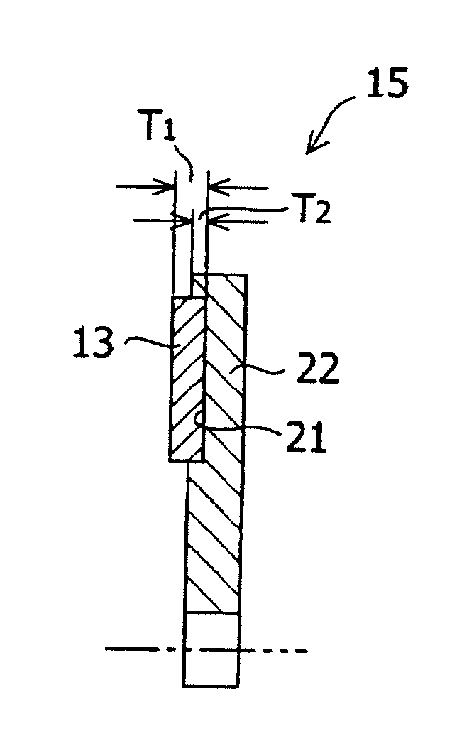
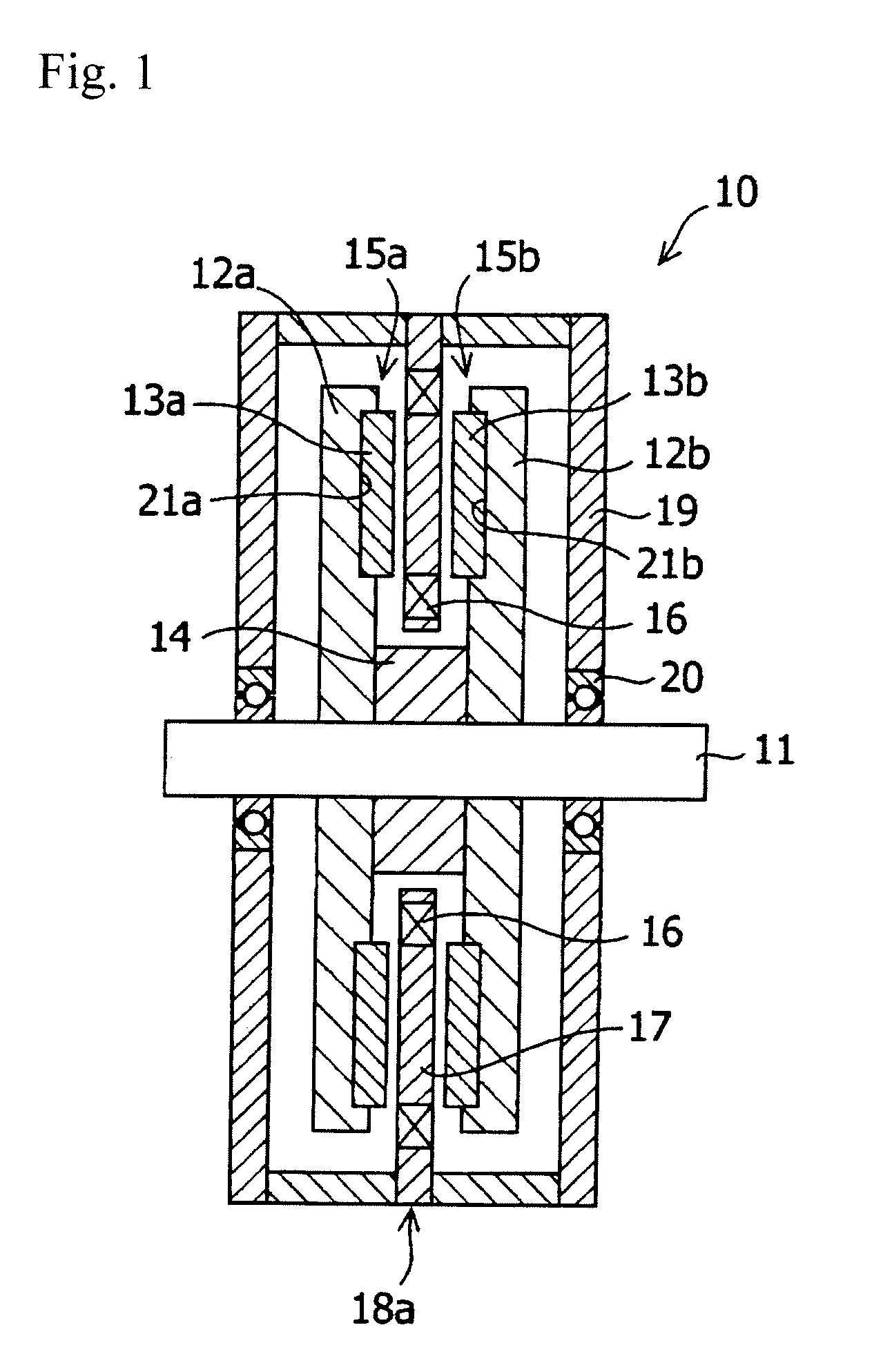
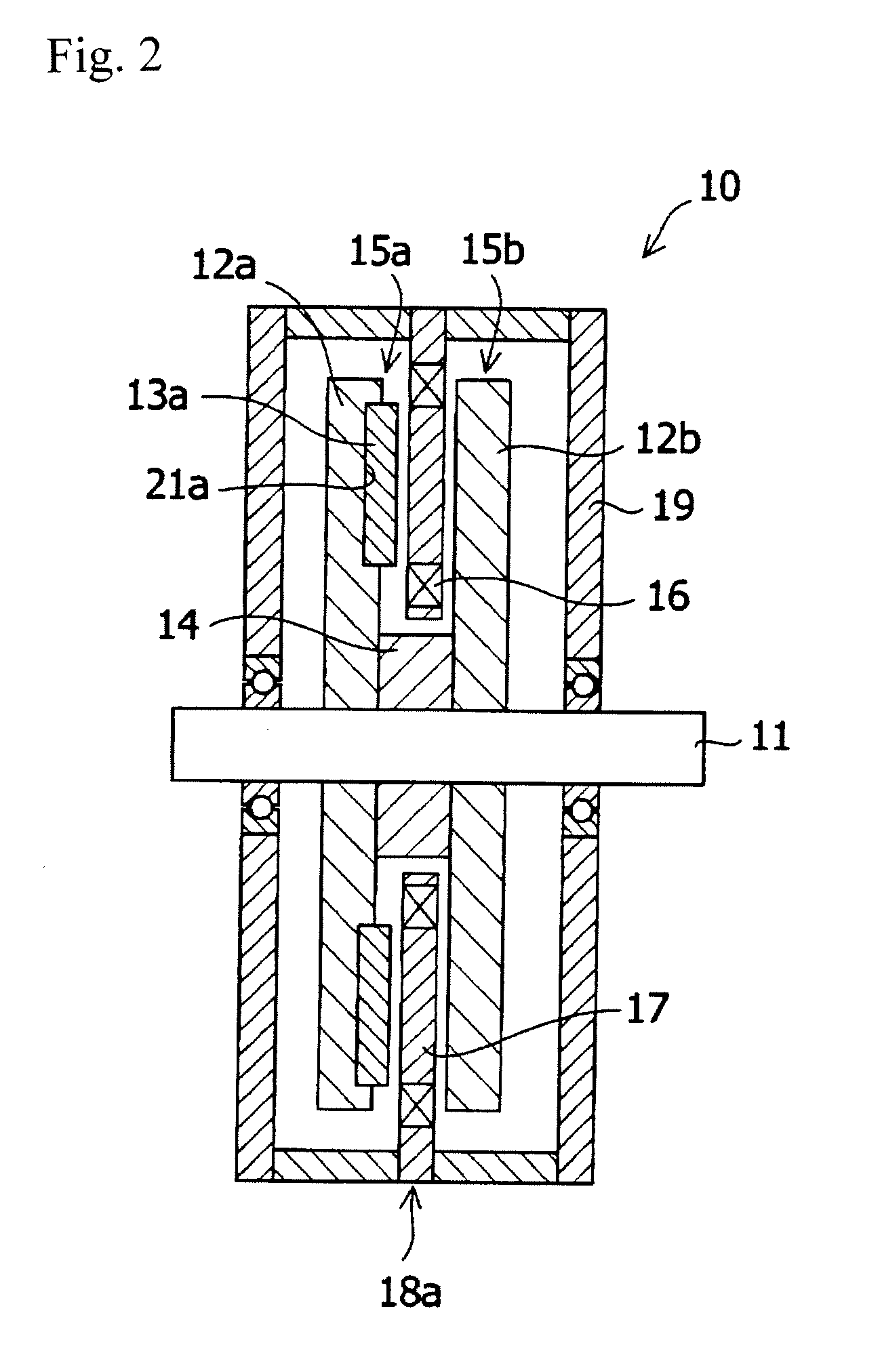
[0079]The configuration of the axial gap type rotating machine of the Embodiment 1 is shown in FIG. 1. The materials and the dimensions were the same as Comparative Example 1 except that the rotor had a structure in which the magnets were disposed at the rotor yoke. As shown in FIG. 5, sixteen magnets 13 were inserted in sixteen concave portions 21 of a rotor yoke 12 formed concentrically in spaced relation to each other, with the pole surfaces being alternately an N pole and an S pole. As shown in FIG. 6, the thickness T1 of the permanent magnet was 4 mm and the fitted length T2 was 2 mm. The magnets 13 and the rotor yoke 12 were bonded by applying elastic adhesive (EP001, manufactured by Cemedine Co., Ltd.) to the side surfaces and the bottom surfaces of the concave portions.

[0080]Next, in the same way as Comparative Example 1, the rotor of the axial gap type rotating machine obtained was rotated at 4000 rpm and used as an electric generator. The effective value of the voltage gen...


PUM


Abstract

An axial gap type rotating machine rigidly fixing the permanent magnets without reducing the magnetic flux and having a high output is provided.
An axial gap type rotating machine having: a housing 19; a rotating shaft 11 rotatably supported in the housing; two rotors (15a, 15b), having rotating disks (12a, 12b) rotatable integrally with the rotating shaft 11 as the central axis, and permanent magnets (13a, 13b) arranged concentrically in spaced relation to each other on at least one side of the surfaces of the rotating disks, wherein the surfaces having the permanent magnets face each other in spaced relation; and a stator 18 that is arranged between the rotors facing each other, the stator is spaced from the rotor, and fixed to the housing, the stator having a plurality of coils 16 disposed concentrically around said rotating shaft in spaced relation to each other; wherein magnetic flux generated from the permanent magnets of the rotors intermittently penetrates the interior of each of the coils 16 disposed concentrically around said rotating shaft 11 as it rotates, wherein the rotating disk has a concave portion 21 in the surface facing the stator and the permanent magnets are disposed at the concave portions so as to protrude above the surface of the rotating disk.

Description

TECHNICAL FIELD[0001]The present invention relates to an axial gap type rotating machine which is a synchronous type permanent magnet rotating machine such as a motor or an electric generator, having its rotors and stators facing each other in the direction of the rotational axis.BACKGROUND ART[0002]Structures of permanent magnet rotating machines can be classified into the radial gap type and the axial gap type. In the radial gap type, a plurality of permanent magnets are arranged in the circumferential direction of a rotor, the poles of the permanent magnets being radially directed, and a stator is arranged so as to face the permanent magnets. Generally the stator has a structure in which coils are wound on an iron core having a plurality of teeth on the surface facing the rotor. By use of an iron core, magnetic flux from the poles of the rotor can efficiently intersect the coils so as to produce a large torque in the case of a motor and a large voltage in the case of an electric ...

Claims


Application Information

Patent Timeline
Patent Type & Authority Applications(United States)
IPC IPC(8): H02K1/18
CPCH02K21/24H02K16/04H02K16/02H02K1/2793H02K1/2798H02K1/27
Inventor MIYATA, KOJIWATANABE, NAOKIHONSHIMA, MASAKATSU
Owner SHIN ETSU CHEM IND CO LTD
Why Eureka
Try Eureka