Suction device

a suction device and vacuum pump technology, applied in the direction of piston pumps, load-engaging elements, safety gear, etc., can solve the problems of negative air pressure, inconvenient portability, and high cost of vacuum pumps,

Inactive Publication Date: 2011-06-28
CHI MEI COMM SYST INC
View PDF4 Cites 10 Cited by
  • Summary
  • Abstract
  • Description
  • Claims
  • Application Information

AI Technical Summary

Problems solved by technology

However, vacuum pumps can be expensive and inconvenient to carry.
Furthermore, the air pipe for the vacuum pump is soft and easily bent during suction.
Bent air pipes often lead to an unstable negative air pressure for the suction tip, thereby degrading the positioning or transferring of the workpieces.

Method used


Image

  • Suction device
  • Suction device
  • Suction device

Examples


Embodiment Construction

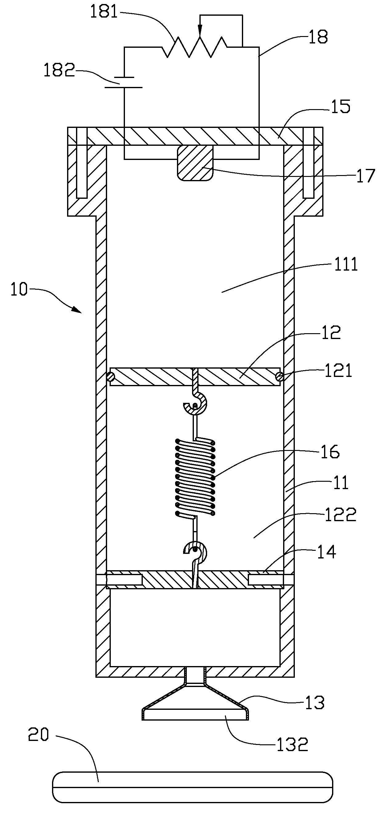
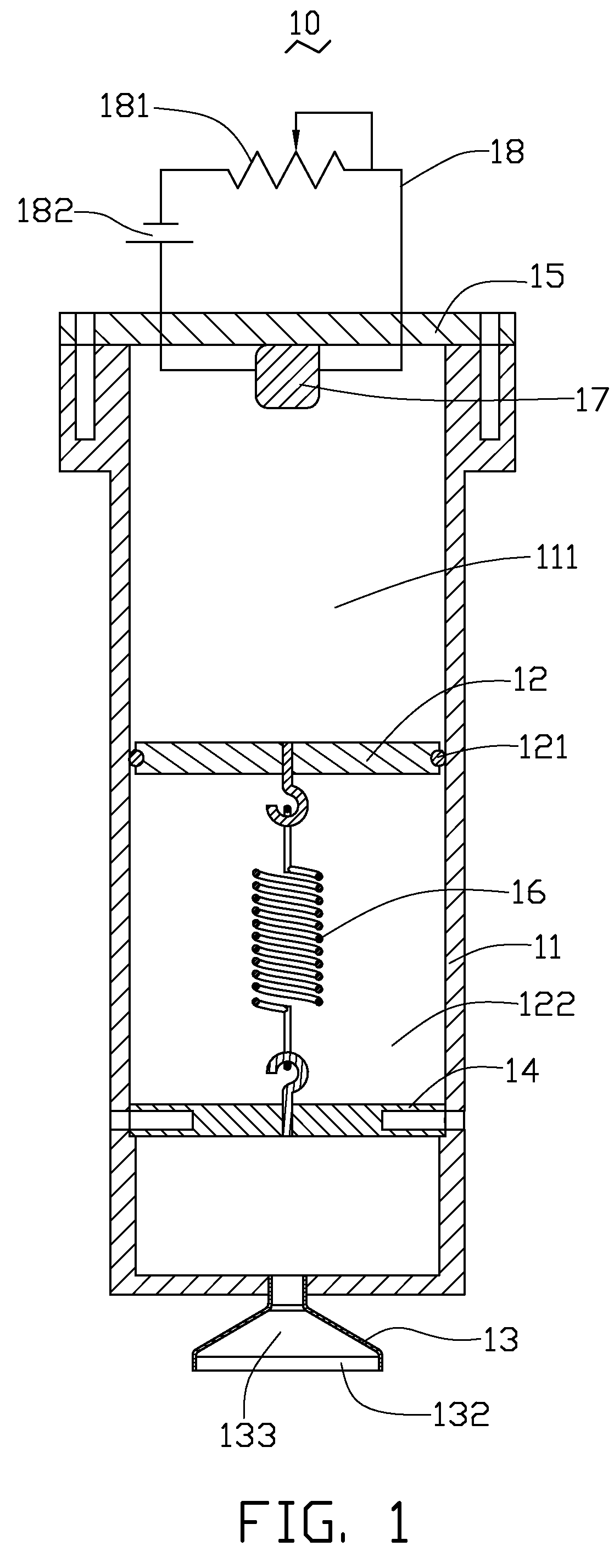
[0014]The exemplary suction device 10 shown in FIGS. 1 through 3 is used to provide suction to position / transfer an electronic device, such as a mobile phone 20 (see FIGS. 5 and 6).

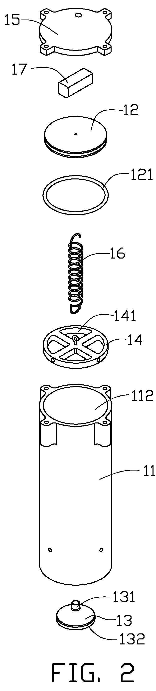
[0015]The suction device 10 includes a cylinder 11, a piston 12, a suction tip 13, a positioning board 14, a cylinder cap 15, an elastic member 16, an electromagnetic member 17, and a controlling circuit 18.

[0016]The cylinder 11 includes an opening end 112, an opposite semi-enclosed end 113 (best seen in FIG. 3) and a chamber 111 formed between the opening end 112 and the semi-enclosed end 113. The semi-enclosed end 113 defines a hole 114.

[0017]The piston 12 can be slidably received in the chamber 111. A seal 121 is arranged between the piston 12 and the cylinder 11 to define a working chamber 122 in the cylinder 11. The piston 12 with the seal 121 divides the cylinder 11 into two parts: the chamber 111 and the working chamber 122. The volume of the working chamber 122 can be adjusted by sliding the pisto...


PUM


Abstract

A suction device (10) is described. The suction device (10) includes a cylinder (11) having a semi-closed end (113), a suction tip (13) connected to the semi-closed end (113), a piston (12), an elastic member (16) and an electromagnetic member (17). The piston (12) is slidably received in the cylinder (11), the piston (12) and the semi-closed end (113) encloses a working chamber (122). One end of the elastic member (16) is connected to the cylinder (11), the other end is connected to the piston (12). The electromagnetic member (17) causes the piston (12) to slide back and forth in the cylinder (11) to vary the volume of the working chamber (122) by adjusting the magnetic field of the electromagnetic member (17).

Description

BACKGROUND[0001]1. Field of the Invention[0002]The present invention relates to suction devices and, particularly, to a suction device using negative air pressure.[0003]2. Description of Related Art[0004]Suction devices are typically used to transfer and position workpieces (e.g., electronic components). The suction device usually includes a vacuum pump, a suction tip and an air pipe. The suction tip has a suction surface which is connected to the vacuum pump via the air pipe such that a negative air pressure is generated to suck workpieces into firm contact with the suction surface.[0005]However, vacuum pumps can be expensive and inconvenient to carry. Furthermore, the air pipe for the vacuum pump is soft and easily bent during suction. Bent air pipes often lead to an unstable negative air pressure for the suction tip, thereby degrading the positioning or transferring of the workpieces.[0006]Therefore, there is room for improvement within the art.BRIEF DESCRIPTION OF THE DRAWINGS[0...

Claims


Application Information

Patent Timeline
Patent Type & Authority Patents(United States)
IPC IPC(8): B66C15/06
CPCB65G47/91B25J15/0616B25J15/0246
Inventor WU, HUNG-CHEN
Owner CHI MEI COMM SYST INC
Why Eureka
Try Eureka