
Electronic device with support legs

a technology of supporting legs and electronic devices, which is applied in the direction of portable computer details, electric apparatus casings/cabinets/drawers, instruments, etc., can solve the problems of internal electronic components that cannot be efficiently dispersed from the main body of the notebook, internal electronic components may be damaged, and the user is not comfortable to operate the notebook

Inactive Publication Date: 2011-08-02
HONG FU JIN PRECISION IND (SHENZHEN) CO LTD +1
View PDF17 Cites 23 Cited by
  • Summary
  • Abstract
  • Description
  • Claims
  • Application Information

AI Technical Summary

Benefits of technology

The patent describes an electronic device with a housing and two supporting mechanisms. The housing has two sloping slide portions that are formed at adjacent corners of the base plate. Each sloping slide portion has an oblique sloping plate. Each supporting mechanism includes a support leg that is slidably connected to the sloping plate. The altitude of each support leg relative to the base plate can change when the support leg moves relative to the sloping plate. The technical effect of this design is that it allows for easier adjustment and positioning of the electronic device, making it more user-friendly and convenient.

Problems solved by technology

However, the keyboard is usually parallel to the tabletop making it very uncomfortable for a user to operate the notebook.
Heat produced by internal electronic components cannot be dispersed efficiently from the main body of the notebook, even though the notebook has a fan for heat dissipation.
As a result, the internal electronic components may be damaged from overheating.
In addition, a gap for emitting heat is formed between the keyboard and the main body.
However, dust and harmful substances may easily get inside the main body through the gap and deposit on the internal electronic components.
This may cause a short circuit of the internal electronic components, and make it difficult to disperse the heat produced by the internal electronic components.

Method used


Image

  • Electronic device with support legs
  • Electronic device with support legs
  • Electronic device with support legs

Examples


Embodiment Construction

[0018]References will now be made to the drawings to describe certain inventive embodiments of the present electronic device, in detail.

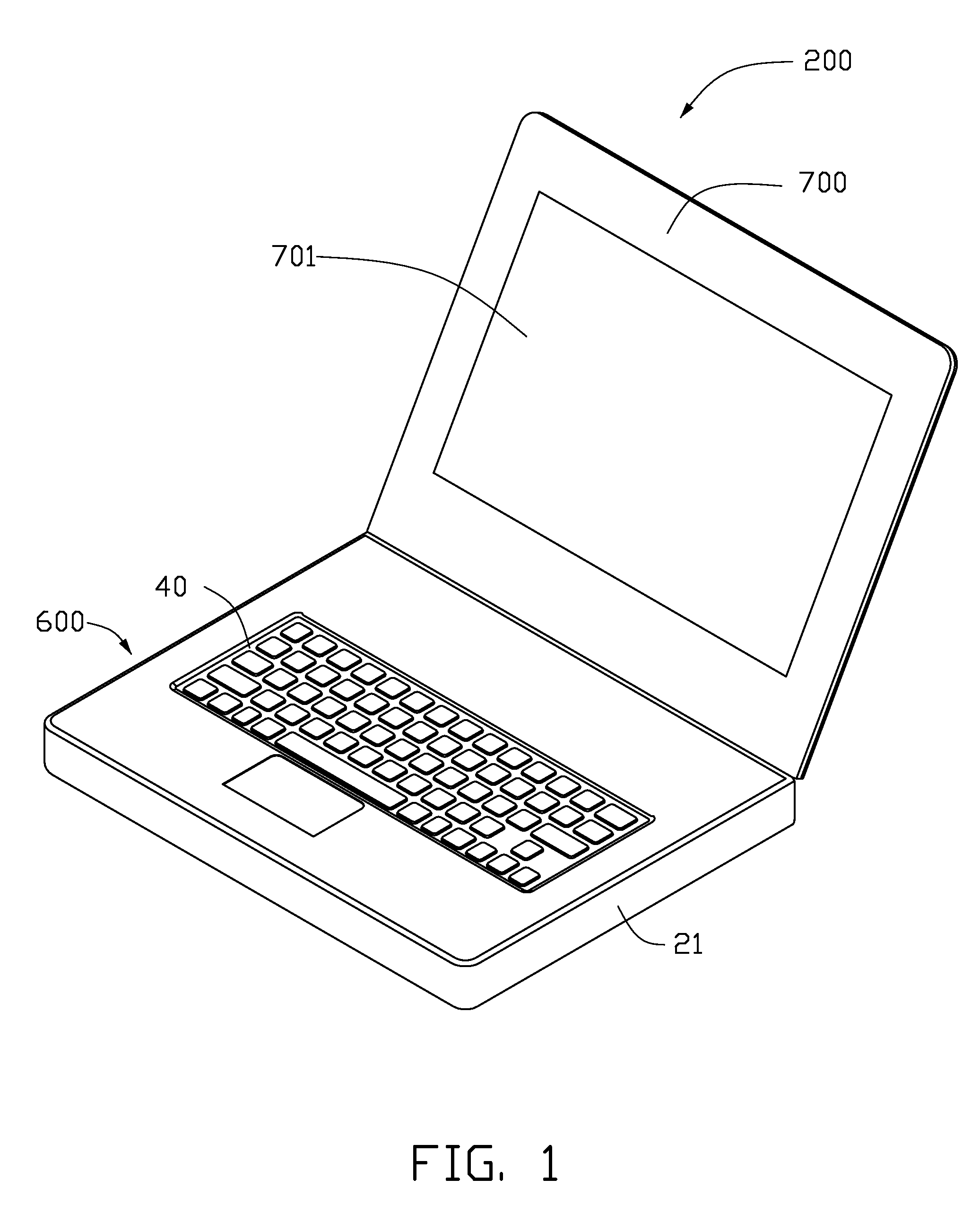
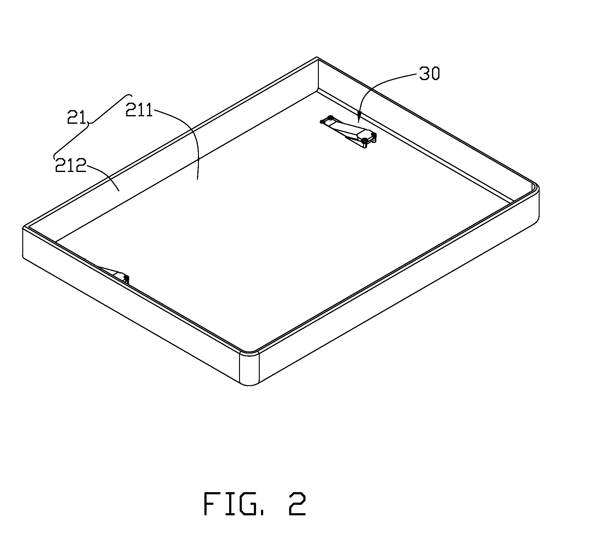
[0019]Referring to FIGS. 1 and 2, a notebook computer 200 in accordance with an embodiment of the present disclosure is shown. The notebook computer 200 includes a main body 600 and a display body 700. The display body 700 is rotatably connected to the main body 600. The main body 600 includes a housing 21, two supporting mechanisms 30, a keyboard 40, and a plurality of electronic components (not shown). The keyboard 40 is assembled in the housing 21. The supporting mechanisms 30 and the electronic components are disposed in the housing 21 below the keyboard 40. The display body 700 includes a display panel 701.

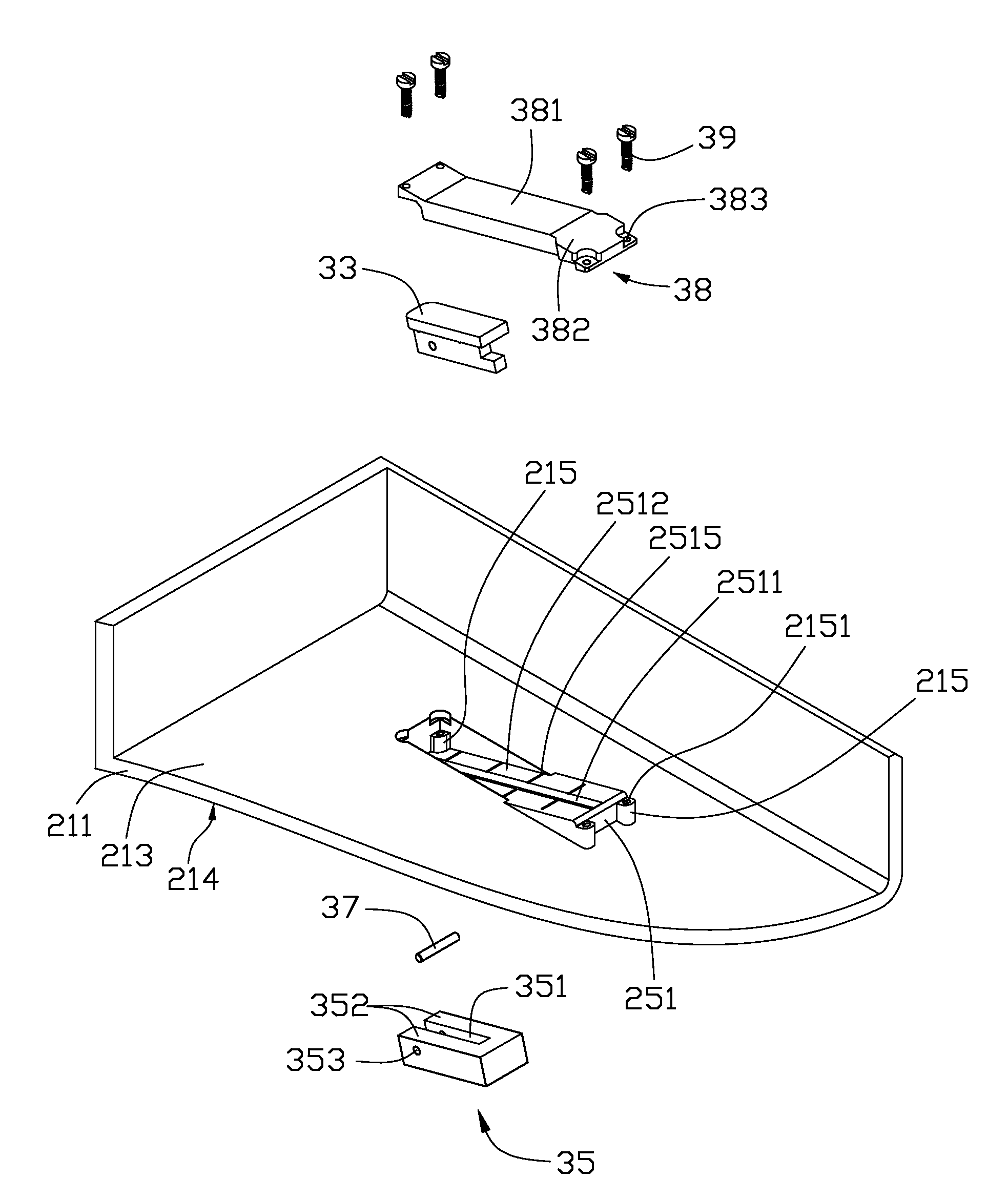
[0020]Referring to FIGS. 2, the housing 21 includes a rectangular base plate 211 and four side plates 212 extending substantially perpendicularly from edges of the base plate 211. Referring also to FIGS. 4 through 6, the base plate 211 includ...


PUM


Abstract

An electronic device includes a housing and two supporting mechanisms. The housing includes a base plate and two sloping slide portions. The sloping slide portions are formed at two adjacent corners of the base plate. Each sloping slide portion has a sloping plate being oblique to the base plate. Each supporting mechanism includes a support leg. Each of the support legs is slidably connected to the sloping plate. An altitude of each of the support legs relative to the base plate is capable of being changed when the support leg moves relative to the sloping plate.

Description

BACKGROUND[0001]1. Field of the Invention[0002]The present disclosure generally relates to electronic devices, and particularly to an electronic device with a main body and a rotatable display body.[0003]2. Discussion of the Related Art[0004]Notebook computers have become popular alternatives to desktop computers because of their portability. A typical notebook computer includes a display body and a main body with a keyboard. The display body is rotatably attached to the main body so that the display body can be opened and closed relative to the main body. In most circumstances, the typical notebook computer is operated on a tabletop. However, the keyboard is usually parallel to the tabletop making it very uncomfortable for a user to operate the notebook. In addition, the main body of the notebook computer is in contact with the tabletop. Heat produced by internal electronic components cannot be dispersed efficiently from the main body of the notebook, even though the notebook has a...

Claims


Application Information

Patent Timeline
Patent Type & Authority Patents(United States)
IPC IPC(8): G06F1/16
CPCG06F1/1616G06F1/166G06F3/0208
Inventor TANG, ZI-MING
Owner HONG FU JIN PRECISION IND (SHENZHEN) CO LTD
Learn More