Plant irrigation apparatus

a plant and watering device technology, applied in the field of plant irrigation, can solve the problem of substantial hollowness of the platform

Active Publication Date: 2011-09-06
STRUCTURAL PLASTICS
View PDF17 Cites 13 Cited by
  • Summary
  • Abstract
  • Description
  • Claims
  • Application Information

AI Technical Summary

Problems solved by technology

Furthermore, the platforms may be substantially hollow such that a void is defined under each platform.

Method used


Image

  • Plant irrigation apparatus
  • Plant irrigation apparatus
  • Plant irrigation apparatus

Examples


Embodiment Construction

[0017]Referring to the drawings, the present invention will now be described in detail with reference to the disclosed embodiment.

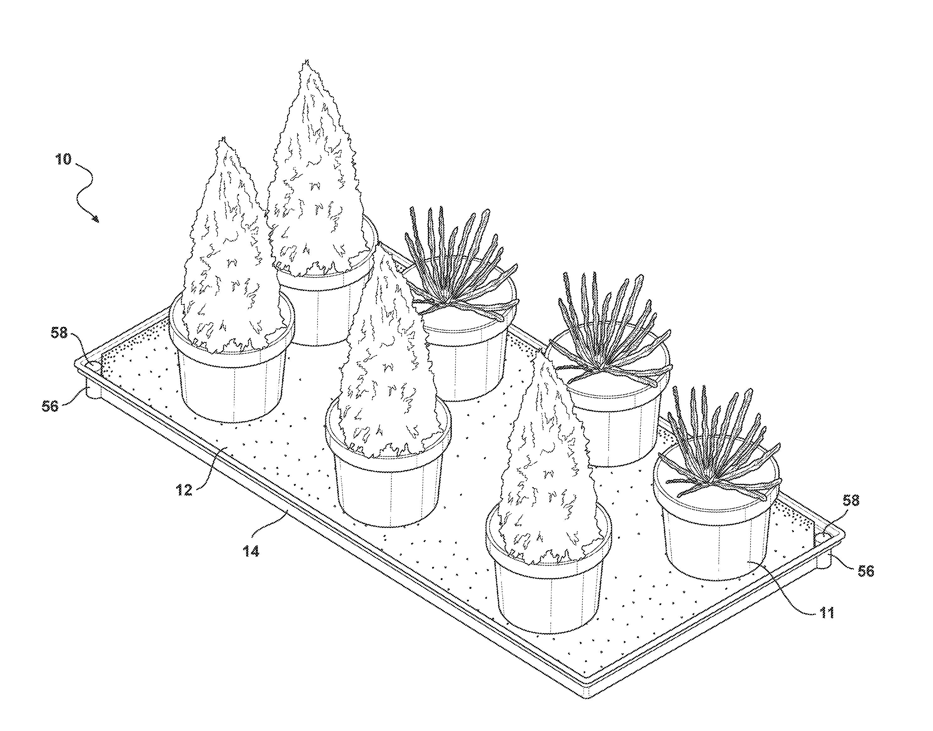
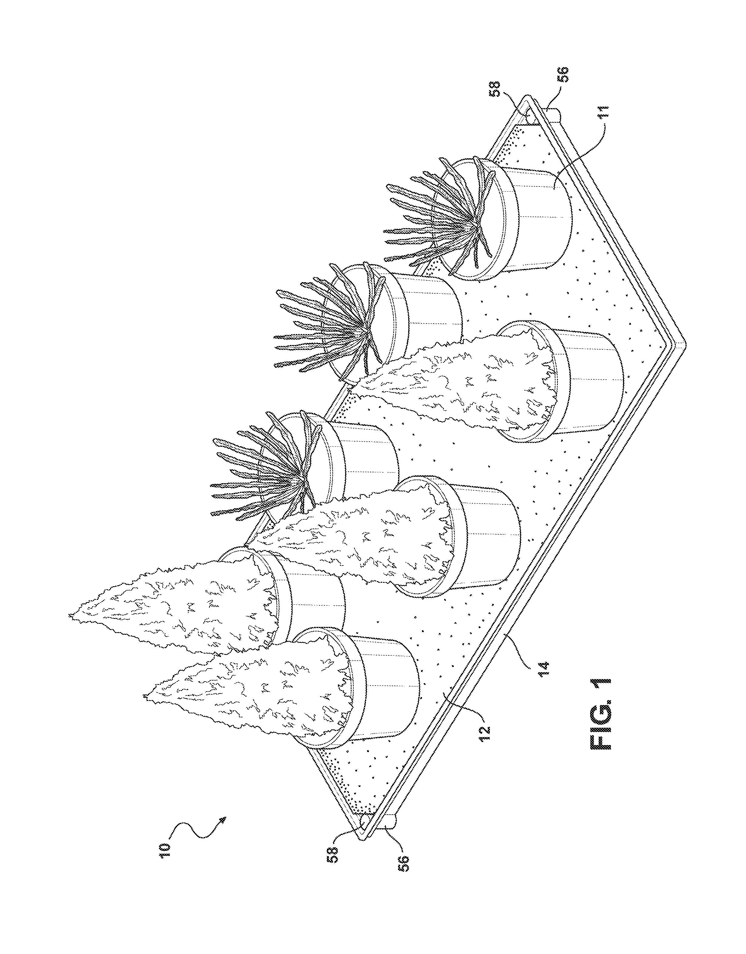
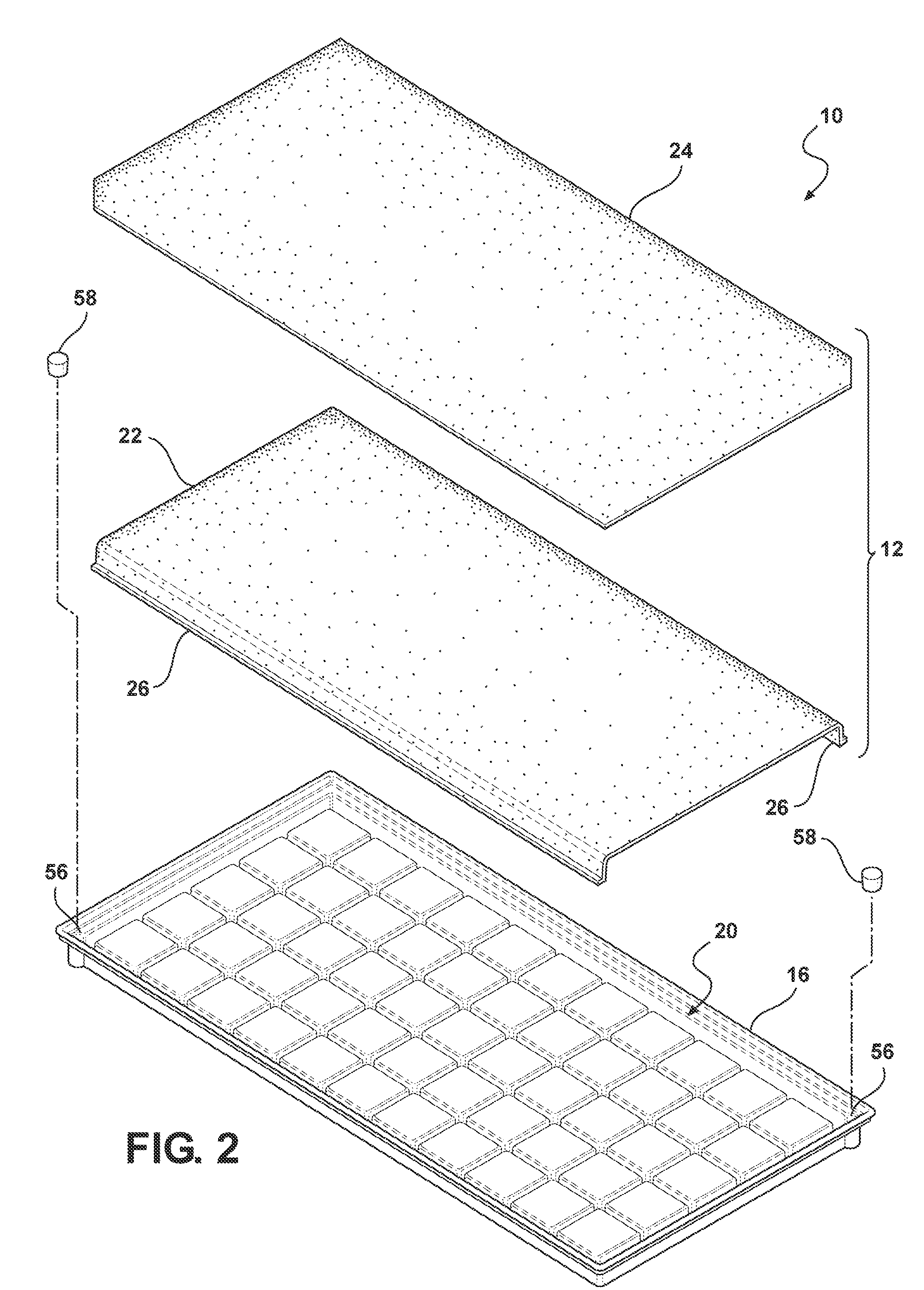
[0018]FIGS. 1-3 show a plant irrigation apparatus 10 according to the present invention for supporting and irrigating potted plants 11. The plant irrigation apparatus 10 includes a capillary irrigation mat 12 that is supported by and within a fluid retaining tray 14. The fluid retaining tray 14 defines a fluid reservoir 16 for containing a fluid 18, such as water or a water / fertilizer solution. A plant support area 20 is disposed at a platform elevation 40 that is above a maximum fluid elevation 42. The capillary irrigation mat 12 is disposed on the plant support area 20, and at least a portion of the capillary irrigation mat 12 is disposed below the maximum fluid elevation 42 such that the capillary irrigation mat is disposed within the fluid reservoir 16 and in contact with the fluid 18.

[0019]The capillary irrigation mat 12 may be any structure capable ...


PUM


Abstract

A plant irrigation apparatus for providing a fluid to one or more plants includes a plurality of platforms that are disposed in an array. Each platform has a support surface that is disposed at a platform elevation. A fluid reservoir for containing the fluid is defined at least partially in between adjacent platforms of the plurality of platforms. At least one fluid-regulating structure is configured to maintain a maximum elevation for the fluid, wherein the maximum elevation for the fluid is lower than the platform elevation. A capillary mat is supported by the plurality of platforms. At least a portion of the capillary mat is disposed within the fluid reservoir below the maximum elevation of the fluid.

Description

FIELD OF THE INVENTION[0001]The invention relates to the field of plant irrigation, and more particularly, the invention relates to a self-contained plant irrigation apparatus having an integral water reservoir.BACKGROUND OF THE INVENTION[0002]In large scale commercial plant-growing operations, it is known to utilize irrigation systems that distribute water to individual plants using a capillary mat. Water is typically supplied to the capillary mat by spray nozzles or perforated tubes that are spaced along the length of the capillary mat. These systems are well-suited to large-scale growing operations and to growing operations where the arrangement and placement of plants is infrequently changed, and large capital investments in infrastructure such as a water distribution system are easily justified.[0003]In small scale plant growing operations, investment in a water distribution system is often difficult to justify, leading to the use of manual labor to water plants. In such situat...

Claims


Application Information

Patent Timeline
Patent Type & Authority Patents(United States)
IPC IPC(8): A01G27/04
CPCA01G9/045A01G27/00A01G27/04
Inventor MASSER, JEREMYJANOWAK, MATT
Owner STRUCTURAL PLASTICS
Why Eureka
Try Eureka