Nasal dilator

a dilator and nasal tube technology, applied in the field of nasal tubes, can solve the problems of breathing difficulty, breathing difficulty, and difficulty in breathing for a person, and achieve the effect of reducing the collapse of the nostril

Active Publication Date: 2011-11-01
INNOVATIVE MEDICAL EQUIP
View PDF99 Cites 85 Cited by
  • Summary
  • Abstract
  • Description
  • Claims
  • Application Information

AI Technical Summary

Benefits of technology

[0009]In still another embodiment, the nasal dilator for temporary attachment to a nose of a person includes an adhesive bridge for spanning transversely across a mid-line of the nose and a pair of downwardly extending bendable hooks connected to the adhesive bridge and insertable into each nostril for reducing nostril collapse.

Problems solved by technology

Resistance within the nasal passage may make it difficult or uncomfortable to breathe or necessary to breathe through the mouth.
This discomfort and / or resistance to breathing may lead to snoring, among other things.
The nasal valve is surrounded by blood vessels, which can easily swell and block the nasal passageway, making breathing more difficult.
The swelling causes a reduction in the cross-sectional area of the nasal passage and may make it more difficult for a person to breathe.
Further, the nostrils may collapse during breathing, especially during times of heavy breathing, which is common during exercise.
The collapse of the nostrils may also be caused by a nasal anatomical abnormality, such as a deviated septum which causes an uneven flow of air through the nostrils.
When the outer wall of the nostril collapses the area through which the air is drawn is reduced, which may make it more difficult and / or uncomfortable to breathe.
While these internal devices may be effective at reducing nostril collapse or dilating the nostrils, they are incapable of dilating both of the internal nasal valves and the nostrils.

Method used


Image

  • Nasal dilator
  • Nasal dilator
  • Nasal dilator

Examples


Embodiment Construction

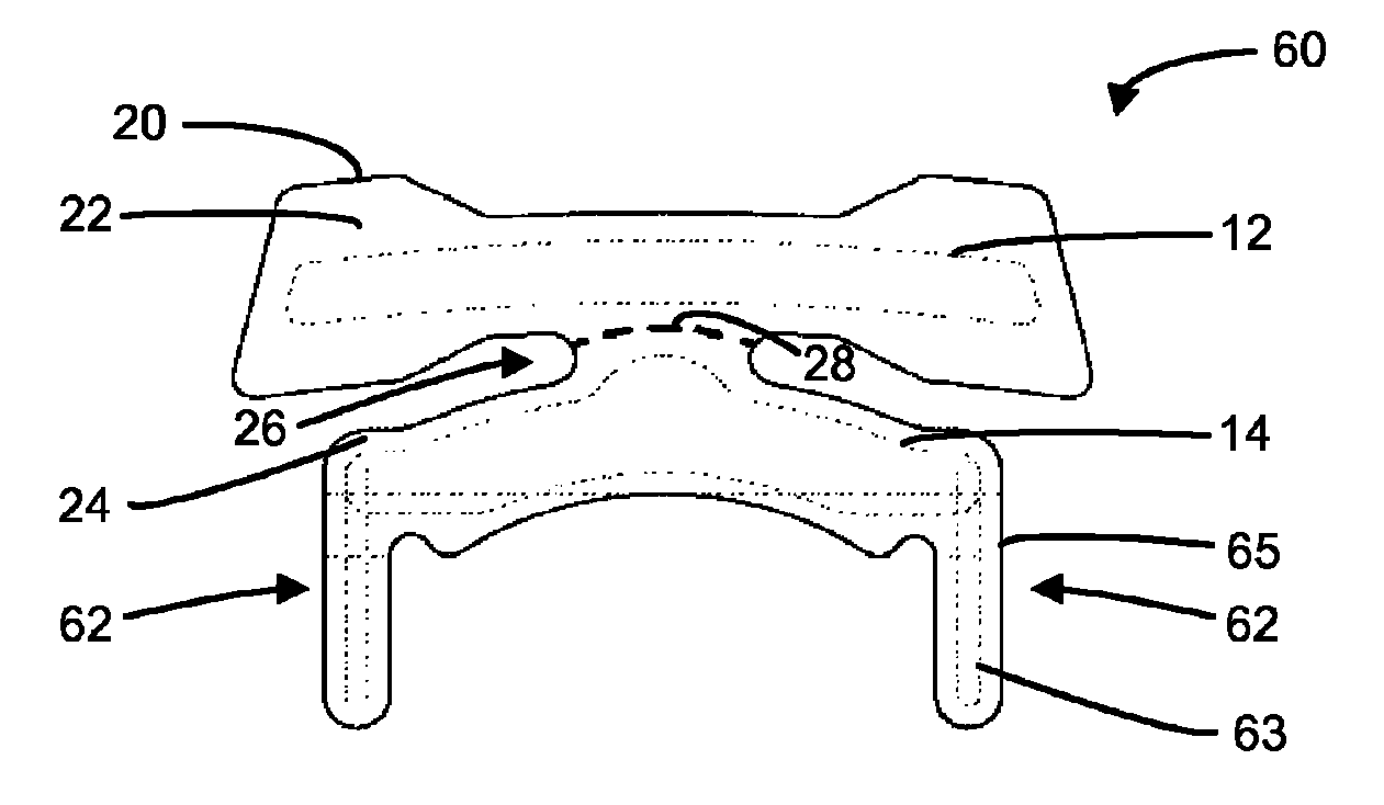
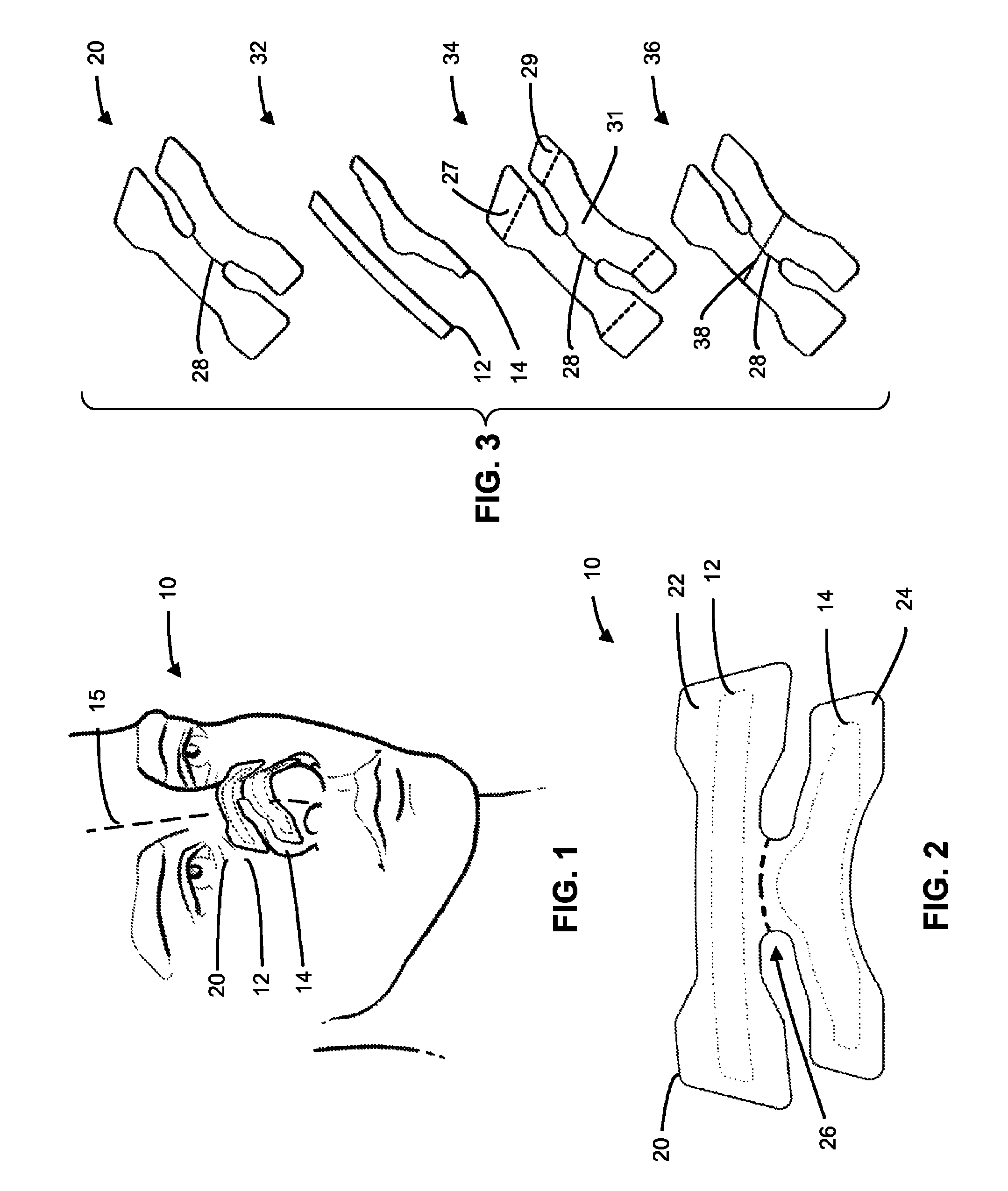
[0046]Referring to the drawings, wherein like reference numbers designate like parts in the several figures, and initially to FIG. 1, one embodiment of a dual truss nasal dilator 10 is shown. The nasal dilator 10 may be attached temporarily to the nose of a person, as shown in FIG. 1.

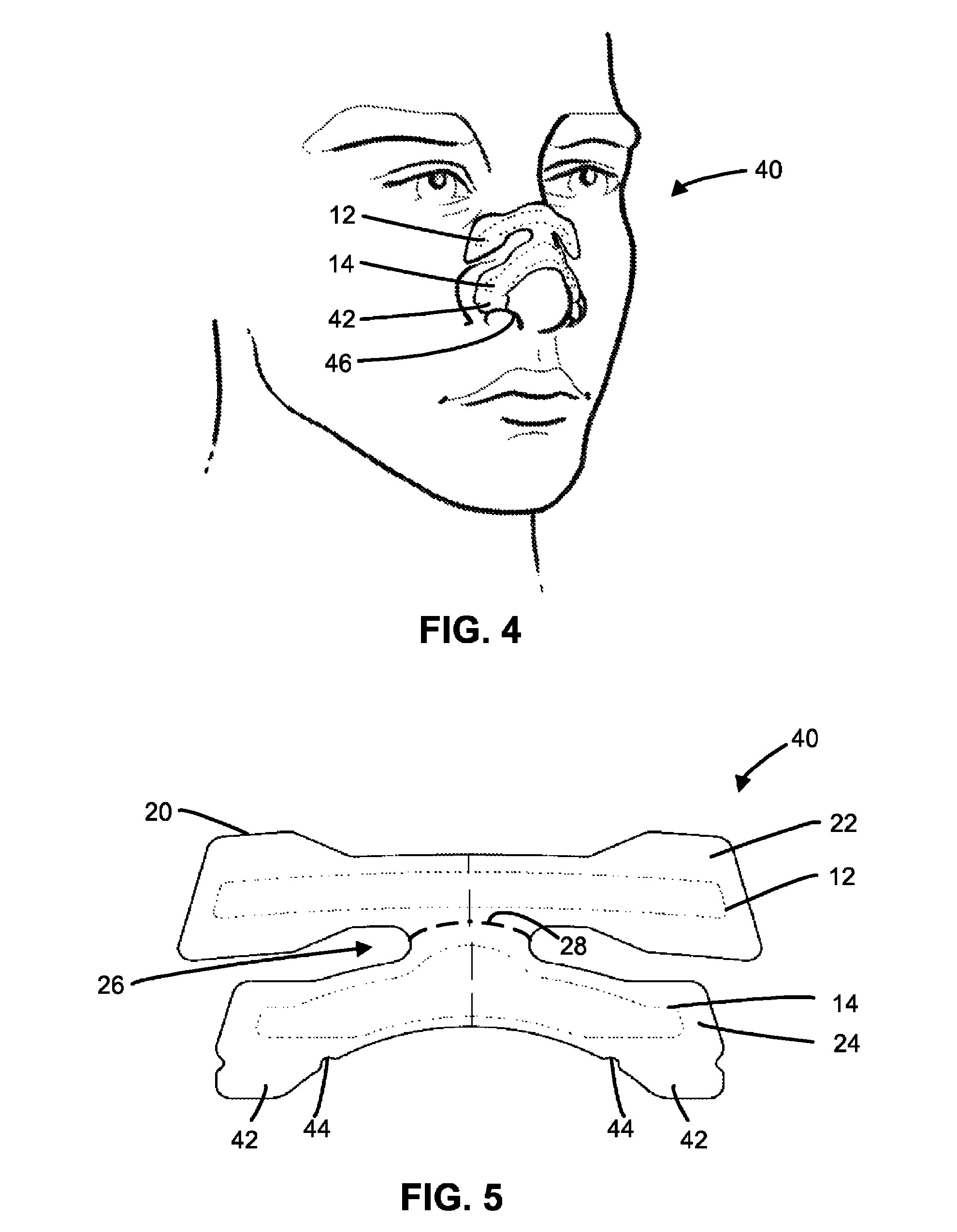
[0047]The nasal dilator 10 has two separate resilient members 12, 14 that extend transversely (e.g., laterally or horizontally) across a mid-line portion 15 of the nose to dilate the nasal valve and the nostrils, respectively. As shown, the upper resilient member 12 extends transversely across an upper portion of the nose, which may include the bony region of the nose. The upper resilient member 12, for example, may be attached temporarily, via the substrate 20, an adhesive, or an adhesive layer, to the skin below the eye orbital, on the cheek, on the sides of the nose, etc.

[0048]The lower resilient member 14 extends across a mid-line portion 15 of the nose below the upper resilient member 12, such as, ...


PUM


Abstract

A nasal dilator that includes an upper resilient member for dilating the nasal valve and a lower resilient member for dilating the nostrils. The upper resilient member and lower resilient member may be attached to one another by a flexible substrate having a middle portion that is narrower in length than the upper or lower resilient members. The nasal dilator also may have adhesive tabs extending downwardly from the lower portion of the substrate on either side of the nose and towards the nostril entry, for temporary attachment to the side of the nasal vestibule to reduce nostril collapse. The nasal dilator also may include bendable or configurable hooks extending downwardly from the lower portion of the substrate and towards the nostril entrance for insertion into the nostril to reduce nostril collapse.

Description

TECHNICAL FIELD[0001]The present invention generally relates to tissue dilators and in particular to a nasal dilator.BACKGROUND OF THE INVENTION[0002]In order to breathe, air may be drawn into the lungs through the nasal passageway, which includes the nostrils and the nasal valve (sometimes referred to as an internal valve). Resistance within the nasal passage may make it difficult or uncomfortable to breathe or necessary to breathe through the mouth. This discomfort and / or resistance to breathing may lead to snoring, among other things. It is well understood that breathing through the nasal passages is much healthier than through the mouth due a series of physiological mechanisms in the nasal passages that help to condition the air prior to it reaching the lungs. These include, among other things, filtering, warming, moisturizing, and dehumidifying the inhaled air prior to being received by the lungs.[0003]The nasal passageway has at least two potential areas of resistance, the int...

Claims


Application Information

Patent Timeline
Patent Type & Authority Patents(United States)
IPC IPC(8): A61M15/00A62B18/00A62B9/00A61M16/00A62B7/00
CPCA61F5/08
Inventor GUYURON, BAHMANPUTHOFF, DANIELHORVATH, JAMIETAMULEWICZ, PAUL
Owner INNOVATIVE MEDICAL EQUIP
Why Eureka
Try Eureka