Lock device

a technology of locking device and wing knob, which is applied in the direction of carpet fasteners, wing knobs, dwelling equipment, etc., can solve the problem of limiting the rotation angle of the handle, and achieve the effect of reliable absorption of actions

Inactive Publication Date: 2011-11-01
GIACINTO RIVADOSSI & LIQUIDAZIONE
View PDF28 Cites 16 Cited by
  • Summary
  • Abstract
  • Description
  • Claims
  • Application Information

AI Technical Summary

Problems solved by technology

The above requirements create a set of structural hindrances inside the seating unit that strongly limit the available angle of rotation for the handle rotation.

Method used


Image

  • Lock device
  • Lock device
  • Lock device

Examples


Embodiment Construction

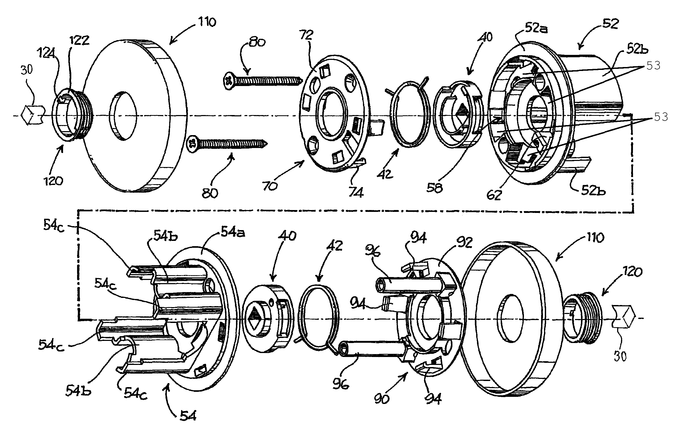
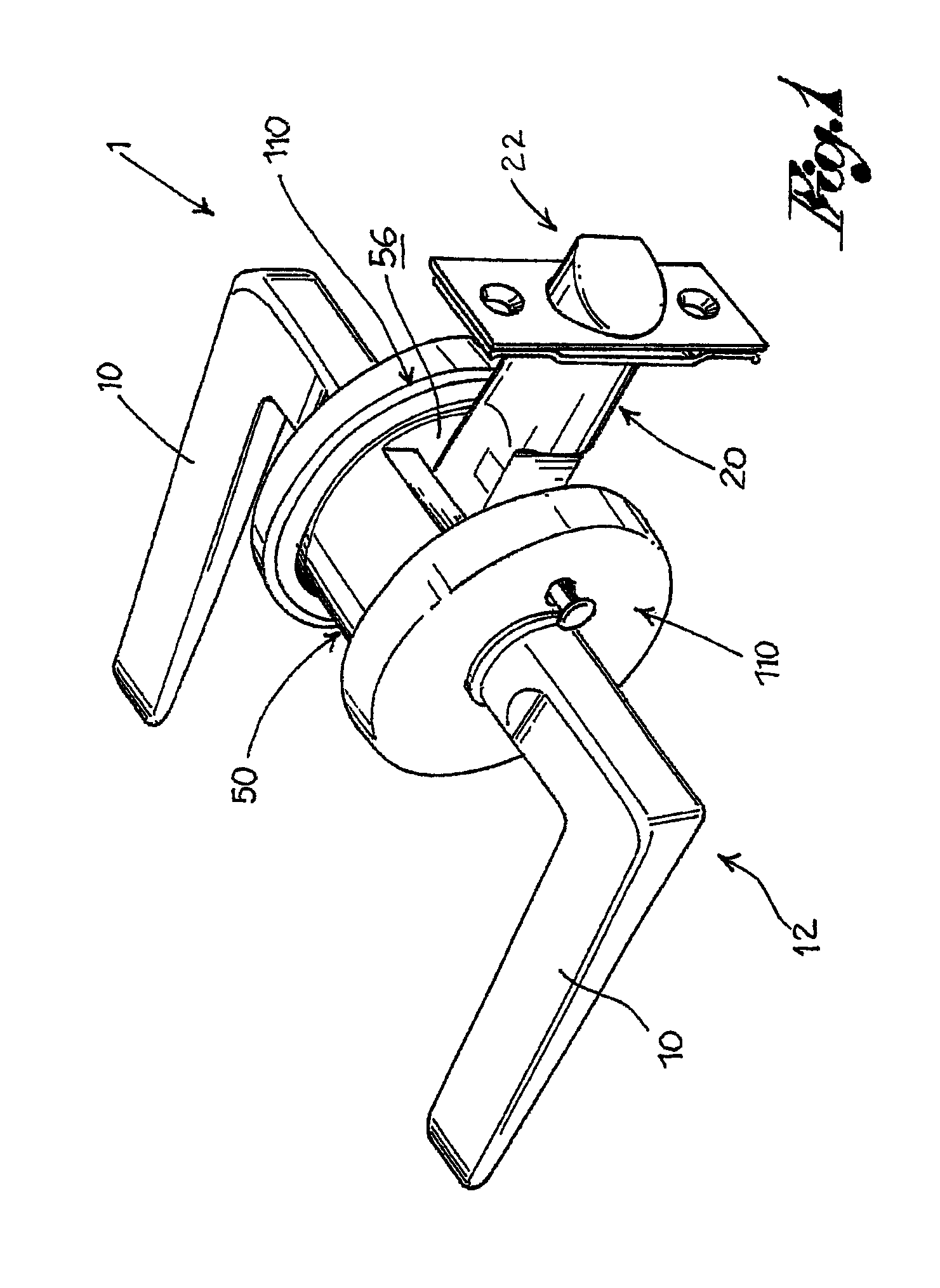
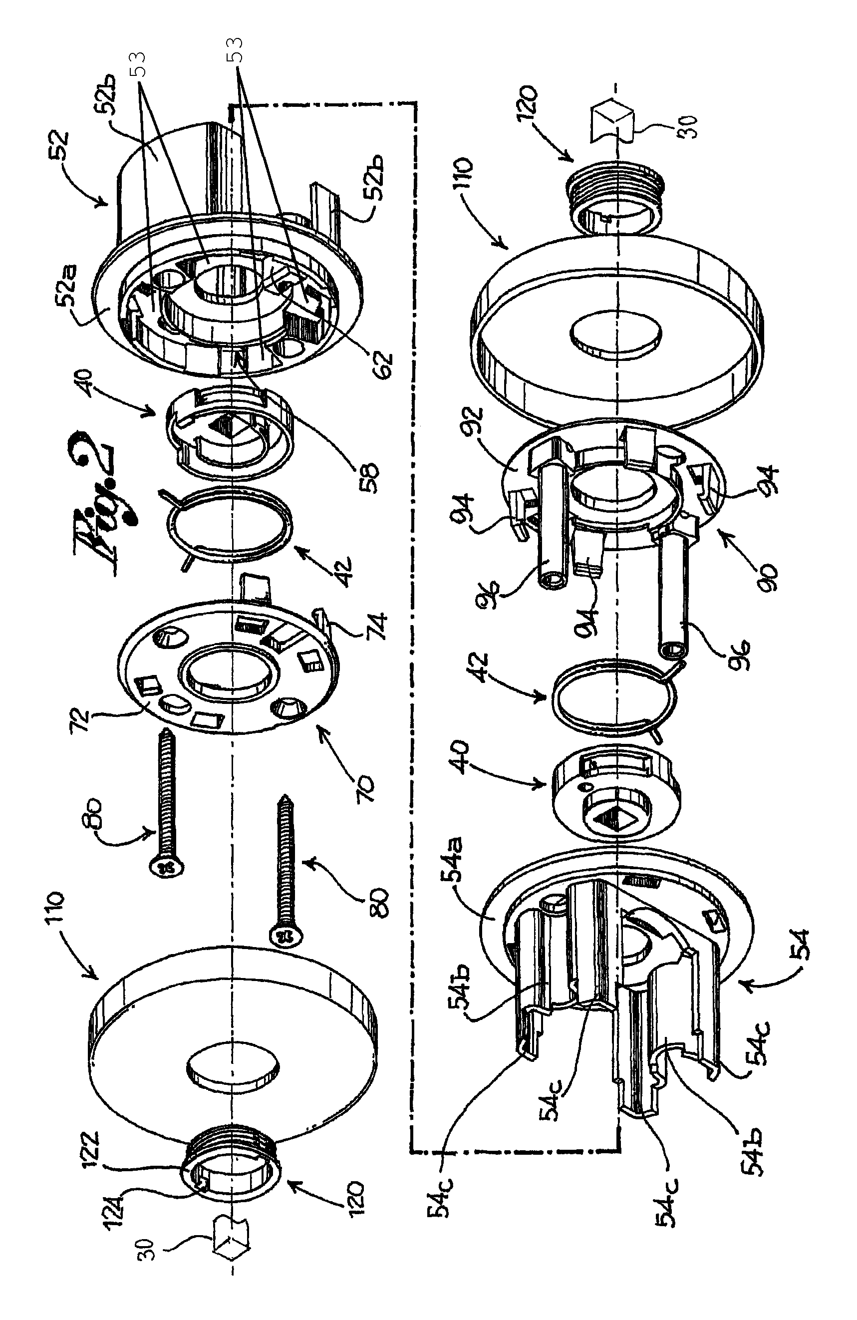
[0030]With reference to the annexed figures, reference numeral 1 globally denotes a lock device for a door.

[0031]Hereinafter, reference is made to an “axial” direction to indicate with such term a direction along the door shutter thickness.

[0032]The lock device comprises at least one handle 10 suitable for being gripped and turned from a rest configuration 12, wherein it remains when it is not influenced by a user, to an actuation configuration, wherein it is turned relative to the previous configuration.

[0033]The lock device 1 further comprises an engagement unit 20 suitable for engaging the door shutter to a jamb thereof in a forward configuration 22 and suitable for releasing the shutter from the jamb in a retracted configuration.

[0034]The lock device further comprises connecting means 30 suitable for mechanically connecting handle 10 with the engagement unit 20, so that the rest configuration 12 of handle 10 corresponds to the forward configuration 22 of the engagement unit 20 a...


PUM


Abstract

The present invention relates to a lock device for a door of the type with seating unit through the door shutter. The seating unit has a first seating body, a second seating body, a first cover and a second cover. There are provided connecting elements, generally self-tapping screws, that engage both the first cover to the first seating body and the second cover, closing the second seating body as a package thereinbetween. Among the other things, the lock device allows a wide rotation of the handle.

Description

[0001]This application is a continuation of International Application No. PCT / IT2006 / 000695, filed Sep. 29, 2006.FIELD OF THE INVENTION[0002]The object of the present invention is a lock device for doors of the type with through seating unit.BACKGROUND OF THE INVENTION[0003]The lock devices of the above type comprise a handle, a square pin, handle return means, an engagement unit and seating unit, placed through the door shutter thickness.[0004]The seating unit is inserted through the door shutter, in an especially made hole. The square pin is inserted through the unit, at the end thereof there are mounted the handles; the return means are seated in the unit and are engaged with the square pin; the square pin is also engaged with the engagement unit, comprising an engagement element, in the jargon called “bolt”, suitable for engaging the door shutter to the jamb thereof, for keeping the door closed.[0005]The seating unit must meet several requirements, to make a durable lock device ...

Claims


Application Information

Patent Timeline
Patent Type & Authority Patents(United States)
IPC IPC(8): E05B15/02E05B3/00
CPCE05B3/065E05B63/006E05C1/163Y10S292/53Y10S292/64Y10T70/5155Y10T70/5832Y10T292/82Y10T292/91Y10T70/5372Y10T292/88Y10T292/57E05B3/06
Inventor PILOTELLI, CARLO
Owner GIACINTO RIVADOSSI & LIQUIDAZIONE
Why Eureka
Try Eureka