Dual glazing panel system

Active Publication Date: 2011-11-15
CPI DAYLIGHTING
View PDF63 Cites 49 Cited by
  • Summary
  • Abstract
  • Description
  • Claims
  • Application Information

AI Technical Summary

Benefits of technology

[0014]In a preferred embodiment the modular panels of the architectural structure include resilient areas along their lateral edges. These resilient areas accommodate lateral expansion and contraction of the modular panels i

Problems solved by technology

It therefore requires substantial skill and is time-consuming to assemble and install panel pairs on-site.
While there are many typically inferior variations on the paired modular panel unit system of FIG. 1, it is indicative of the relative complexity of assembling and installing sloped glazing, skylights

Method used


Image

  • Dual glazing panel system
  • Dual glazing panel system
  • Dual glazing panel system

Examples


Embodiment Construction

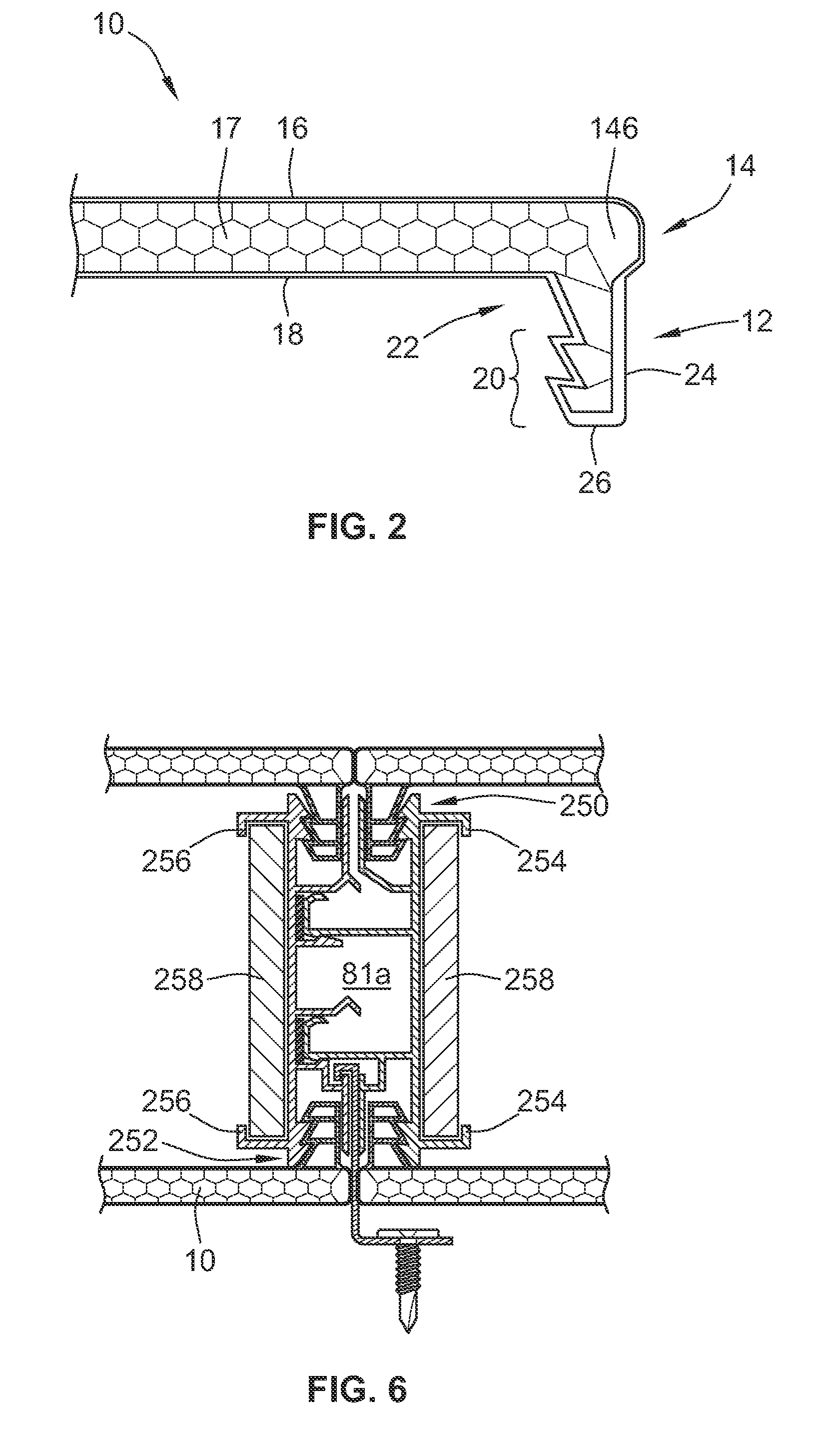
[0026]Turning now to FIG. 2, a single modular upstanding seam flange panel 10 is shown in cross-section, with a seam flange 12 at its distal end 14. The seam flange extends along the entire length or lateral edge of the panel which may be, for example, up to 40 feet in length and from 2 to 4 feet in width. A second flange will be located along the opposite edge of the modular panel parallel to flange 12. Of course, the panels may be provided in other sizes if desired.

[0027]Modular panel 10 may be extruded from polycarbonate (or other resin) and may have a plurality of internal cells in a honeycomb configuration 17 (or other configuration) disposed in the interior of the panel between its outer surface 16 and its inner surface 18. Modular panels 10 with this upstanding seam flange design are known in the art and described for example in U.S. Pat. No. 6,164,024, which is incorporated by reference for purposes of describing the panels and installations in which they may be used. Modula...


PUM


Abstract

A transparent or translucent modular upstanding seam flange panel unit comprising opposed seam flange panels mounted in metal male and female locking engagement members designed to interlock and provide an internal gutter for collecting infiltrating water and for accommodating lateral expansion and contraction of the panels as well as a method for erecting an architectural structure for passing sunlight into an interior region of a building using such panel units.

Description

CROSS-REFERENCE TO RELATED PATENT APPLICATION[0001]This patent application claims the benefit of U.S. Provisional Patent Application No. 61 / 045,818, filed Apr. 17, 2008.FIELD OF THE INVENTION[0002]This invention pertains to modular upstanding seam flange glazing panels for architectural structures and, more particularly, to systems for assembling such modular upstanding seam flange panels into unique paired glazing panel units and for installing the units in sloped glazing, skylights, roofs, walls, and other architectural structures in ways not heretofore imagined.BACKGROUND OF THE INVENTION[0003]Extruded modular panels with upstanding seam flanges made of polycarbonate and other resins are widely used in the design of various architectural structures because they are a strong, lightweight alternative to traditional materials, like glass, which they often replace. For example, such modular glazing panels joined along abutting upstanding seam flanges that extend along their edges can...

Claims


Application Information

Patent Timeline
IPC IPC(8): E06B7/14E06B3/988
CPCE04D3/28E04D3/35E04D3/352E04D3/355E04D3/357E04D2003/285
Inventor KONSTANTIN, MOSHE
Owner CPI DAYLIGHTING
Why Eureka
Try Eureka