
Erogenic stimulator with loop end

a loop end and stimulator technology, applied in non-surgical orthopedic devices, physical therapy, massage, etc., can solve the problems of device self-retention and undesirable delay, and achieve the effect of stimulating the erotic area of both users

Active Publication Date: 2011-11-22
CANNON CATHERINE
View PDF9 Cites 13 Cited by
  • Summary
  • Abstract
  • Description
  • Claims
  • Application Information

AI Technical Summary

Benefits of technology

[0006]It is thus an object of the present invention to provide a marital or sexual aid that is capable of simultaneously stimulating the erotic areas of both users.
[0007]It is a further object of this invention to provide an aid that is self-retaining such that straps or other holding devices are not required, thereby eliminating any delay and discomfort.

Problems solved by technology

Unfortunately, because of the co-linear nature of these opposite shapes, the simultaneous use of such a device by two partners requires some gymnastic-like maneuvers.
Also, it is common for these devices to not be self-retaining, that is, when one end is retained in the vagina or anal cavity, the other end is free to stimulate the other person.
However, fastening such straps prior to use is cumbersome and discomforting and causes undesirable delay.

Method used


Image

  • Erogenic stimulator with loop end
  • Erogenic stimulator with loop end
  • Erogenic stimulator with loop end

Examples


Embodiment Construction

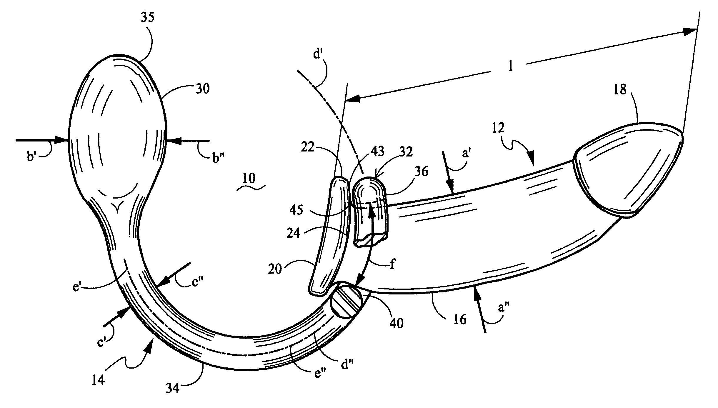
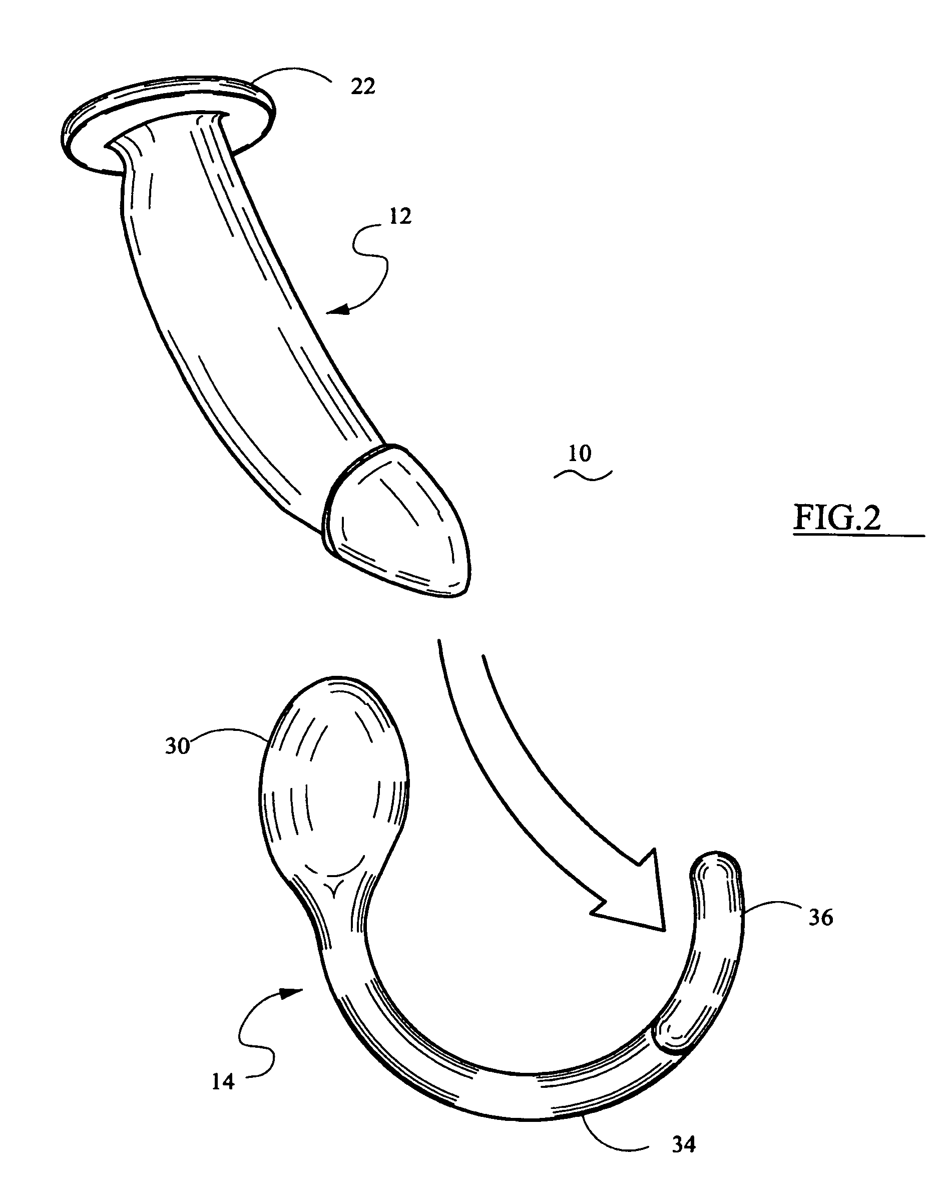
[0022]The present invention relates to a two piece erogenic stimulator or an erogenic stimulator hanger wherein a phallic body is hung in an annulus on a U-shaped member.

[0023]Similar numbers designates similar items throughout the drawings and the specification.

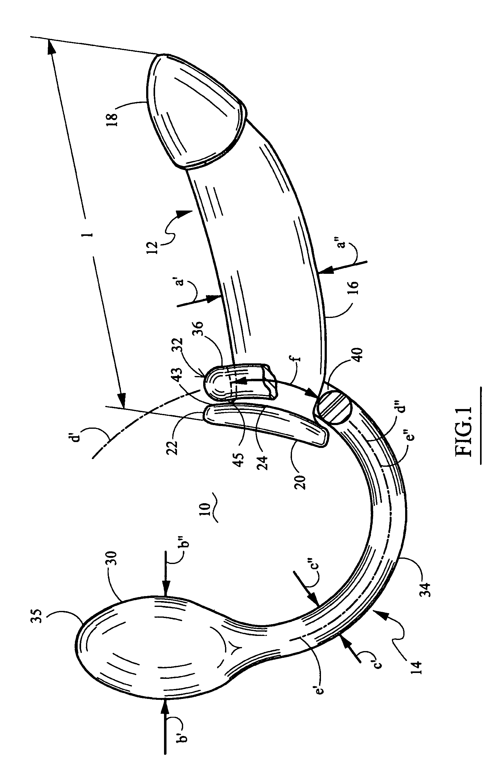
[0024]FIG. 1 diagrammatically illustrates a two piece erogenic stimulator 10 which includes a first elongated generally cylindrical phallic body 12 and a second, generally U-shaped member 14. Generally cylindrical phallic body member 12 may be curved or may be designed with a single longitudinal axis. However, as discussed later, the maximal cross-sectional dimension of body member 12 must be smaller than the opening of the annulus or ring at the end of U-shaped member 14. Although the basic concept herein is that maximal cross-sectional dimension of body member 12 must be smaller than the opening of the annulus or ring (or, stated otherwise, the open cross-sectional dimension of the annulus is greater than the maximal cross...


PUM


Abstract

The erogenic stimulator may be a two-piece stimulator for use by two partners or may be an erogenic stimulator hanger for a phallic body member. The phallic body member includes a distal end and a proximal base end with one or more radial flange elements. The second member (sometimes referred to as the hanger) has a bulbous proximal end portion, sized for receipt in an anal or vaginal cavity, a U-shaped curved stem leading a distal annulus. The annulus has an opening with a cross-sectional dimension greater than the maximal cross-sectional dimension of the phallic body member. The phallic body member is inserted and hung on the annulus of the U-shaped second member-hanger. The inboard face of the annulus abuts the inboard face of the flange elements of the cylindrical body member.

Description

[0001]The present invention relates to an erogenic stimulator configured as a two-piece system with a first elongated generally cylindrical and phallic body hung in an annulus on a second U-shaped member which U-shaped member has an opposing bulbous end portion or configured as erogenic stimulator hanger wherein the phallic body is hung in an annulus on a second U-shaped member formed as a hanger.BACKGROUND OF THE INVENTION[0002]This invention pertains to sexual or erogenous stimulation devices in general and, more particularly, to a self-retained device for simultaneous use by two sexual partners such that the erotic areas of both such users are concurrently excited.GENERAL BACKGROUND[0003]Marital or sexual aids have been known and used throughout the centuries. Generally, such aids have been designed either for self-stimulation or for the stimulation of one party only. However, some aids satisfy two partners at the same time. This latter type of aid or stimulators is designed prim...

Claims


Application Information

Patent Timeline
IPC IPC(8): A61F5/00
CPCA61H19/44A61H19/50A61H21/00A61H19/40A61H2205/086
Inventor CANNON, CATHERINEKAIN, MELISSA MIA
Owner CANNON CATHERINE
Learn More