Erogenic stimulator

a stimulator and erogenous technology, applied in non-surgical orthopedic devices, physical therapy, massage, etc., can solve the problems of device not self-retention and undesirable delay, and achieve the effect of enhancing sexual play and reducing the diameter

Active Publication Date: 2009-05-12
KAIN MELISSA MIA MS
View PDF8 Cites 45 Cited by
  • Summary
  • Abstract
  • Description
  • Claims
  • Application Information

AI Technical Summary

Benefits of technology

[0006]It is thus an object of the present invention to provide a marital or sexual aid that is capable of simultaneously stimulating the erotic areas of both users.
[0007]It is a further object of this invention to provide an aid that is self-retaining such that straps or other holding devices are not required, thereby eliminating any delay and discomfort.
[0010]Yet another object of this invention is to provide an aid that is smoothly contoured for comfort.
[0012]A further object of the present invention is to develop a suction chamber which co-acts with the suction element thereby enhancing the sexual play with the stimulator.SUMMARY OF THE INVENTION
[0013]In one embodiment, the erogenic stimulator includes a first elongated, resilient, cylindrical end region (typically a phallic shape) with a first end extending from a proximal base end and a second resilient, cylindrical, bulbous end region also extending from a proximal base end. The bulbous distal end is connected via a reduced diameter neck to that base. The base is further connected to the first end region. The base, the first phallic end and the second bulbous end extend upwards from the base forming a truncated substantially U-shaped stimulator. The stimulator includes a concave suction element on the base in a curved portion of the truncated U-shape. Other features include: a passageway from that bottom of the concave suction element through said base, into which may be inserted either a plug or a vibratory element. The plug / vibratory element closes the base end of the passageway thereby permitting expansion and contraction of the passageway dependent upon a predetermined condition of the suction opening of the passageway. If the suction element contacts the skin or erogenous region of one user and the plug / vibratory element blocks the passageway, a rocking or undulation of the stimulator suctions and evacuates, alternatively, air through the suction opening of the passageway. This suction and evacuation of air further energizes the skin or erogenous region of the user. The base may have a cut-away for removal of the plug / vibratory element.

Problems solved by technology

Unfortunately, because of the co-linear nature of these opposite shapes, the simultaneous use of such a device by two partners requires some gymnastic-like maneuvers.
Also, it is common for these devices to not be self-retaining, that is, when one end is retained in the vagina or anal cavity, the other end is free to stimulate of the other person.
However, fastening such straps prior to use is cumbersome and discomforting and causes undesirable delay.

Method used


Image

  • Erogenic stimulator
  • Erogenic stimulator
  • Erogenic stimulator

Examples


Embodiment Construction

[0023]The present invention relates to a erogenic stimulator or martial aid.

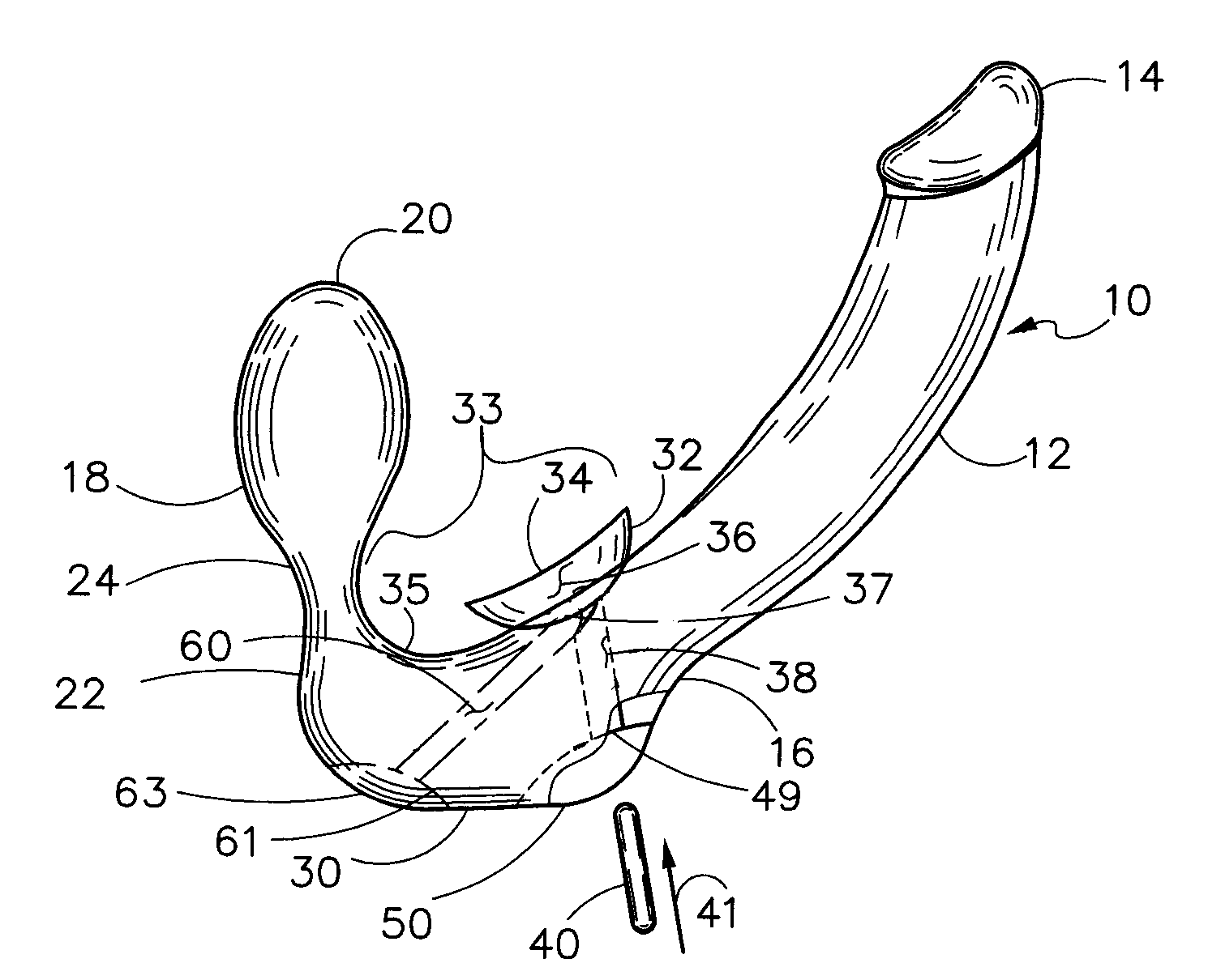
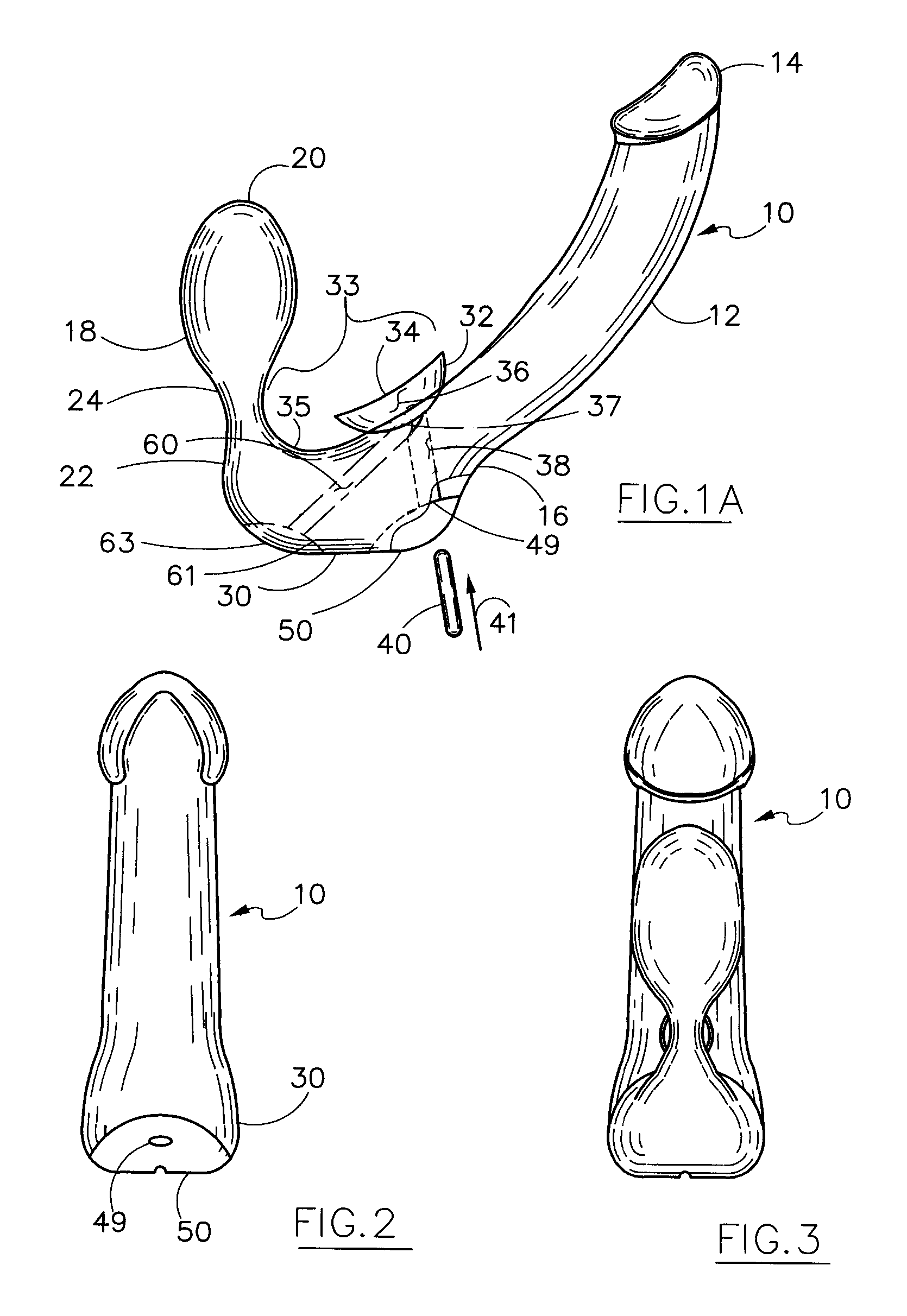
[0024]Similar numerals designate similar items throughout the drawings and specification. FIG. 1A diagrammatically illustrates stimulator 10 having a first elongated, resilient and generally cylindrical end region 12. In the preferred embodiment, end region 12 has a phallic shape. First end region includes a first distal end 14 and a first proximal base end generally identified at end portion 16. Stimulator 10 includes a second resilient and generally cylindrical end region 18 sized for receipt in an anal or vaginal cavity. Second end region 18 includes a second bulbous distal end 20 and a second proximal base end generally near portion 22. This bulbous distal end 20 is connected via a reduced diameter neck portion or neck 24 between the bulbous end 20 and the second proximal base end 22. The second end region includes the bulbous element, the neck and the base end 22. Neck 24 enables bulbous end region 20 t...


PUM


Abstract

The erogenic stimulator includes a first resilient end region (phallic) extending from a base and a second resilient bulbous end region extending therefrom. The bulbous end is connected via a reduced diameter neck to the base. The base and first and second ends form a truncated substantially U-shaped stimulator. A concave suction element is formed on the base in the curved portion of the U-shape. A passageway may be included from the concave suction element through the base into which may be inserted either a plug or a vibratory element. The plug / vibratory element closes the base end of the passageway thereby permitting expansion and contraction of the passageway dependent upon a predetermined condition at the suction opening of the passageway. If the suction element contacts the skin or an erogenous region and blocks the passageway, the rocking stimulator suctions and evacuates, alternatively, air through the suction opening of the passageway.

Description

[0001]The present invention relates to an erogenic stimulator with a suction cup and optionally with an associated chamber for either suction control or insertion of a vibrating unit.BACKGROUND OF THE INVENTION[0002]This invention pertains to sexual or erogenous stimulation devices in general and, more particularly, to a self-retained device for simultaneous use by two sexual partners such that the erotic areas of both such users are concurrently excited.GENERAL BACKGROUND[0003]Marital or sexual aids have been known and used throughout the centuries. Generally, such aids have been designed either for self-stimulation or for the stimulation of one party only. However, some aids satisfy two partners at the same time. This latter type of aid or stimulators is designed primarily for use by a female user and often incorporates a flexible phallic shaped stimulator secured to a base. Variations of this type of stimulator include two such phallic shapes linearly secured to opposite sides of...

Claims


Application Information

Patent Timeline
Patent Type & Authority Patents(United States)
IPC IPC(8): A61F5/00
CPCA61H19/34A61H19/44A61H21/00A61H23/0263A61H9/0057
Inventor KAIN, MELISSA MIA
Owner KAIN MELISSA MIA MS
Why Eureka
Try Eureka