Safety nailing device

a safety nailing and nailing technology, applied in the direction of nailing tools, stapling tools, manufacturing tools, etc., can solve the problems of dents or holes, handle jamming, and user confusion, and achieve the effect of preventing dents or holes

Inactive Publication Date: 2011-12-13
APEX MFG
View PDF3 Cites 13 Cited by
  • Summary
  • Abstract
  • Description
  • Claims
  • Application Information

AI Technical Summary

Problems solved by technology

However, some users do not understand the stop of the handle (15) is purposely designed to prevent the accidental percussion.
On the contrary, they may consider that the handle is jammed because of rusted joints, thus they press the handle harder and harder until one of the handle, the retainer and the striker plate breaks.
As a result, the object, such as paper, leather or cloth, will have defects such as dents or holes.
In addition, such nailing device is not adapted for the user to operate single-handedly and steadily in order to overcome the elastic energy while pressing the blade.

Method used


Image

  • Safety nailing device
  • Safety nailing device
  • Safety nailing device

Examples


Embodiment Construction

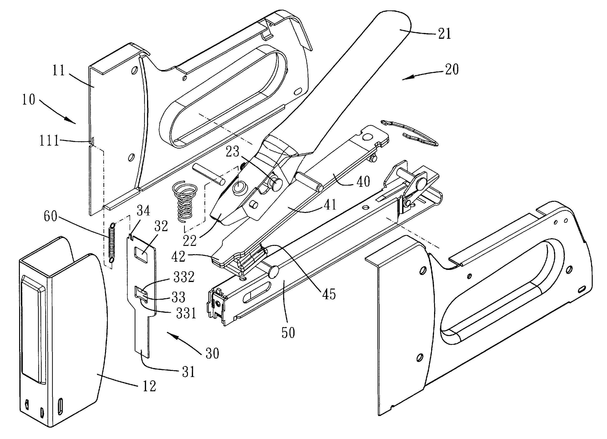
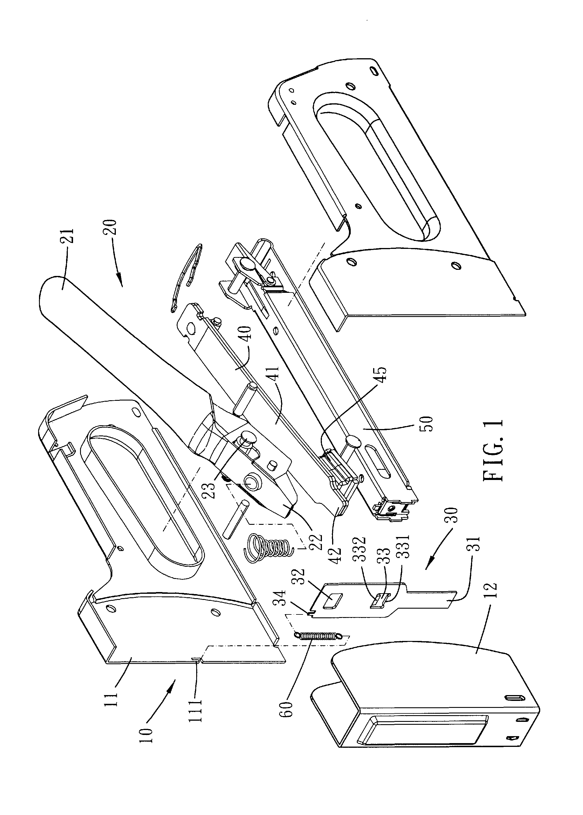
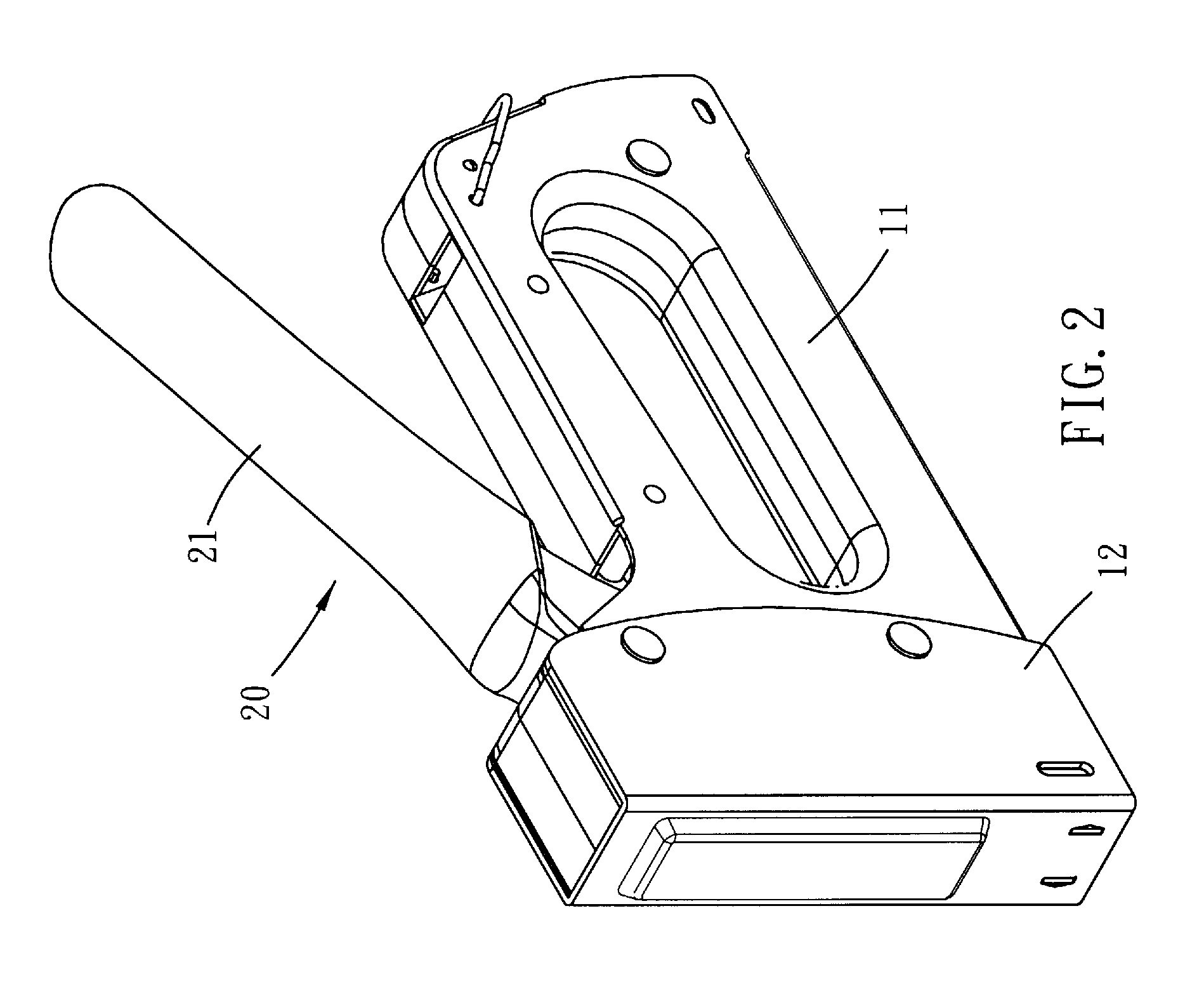
[0022]Please refer to FIG. 1 and FIG. 2 for a preferred embodiment of the present invention. A safety nailing device of the present embodiment includes a main body 10, an actuator 20, a striking plate 30, a leaf spring 40, a magazine 50 and a disengaging means.

[0023]The main body 10 substantially consists of two side plates 11 and a front plate 12, and defines a chamber between the side plates 11 and the front plate 12. An opening is defined on a bottom surface of the main body 10 to communicate the chamber with the surrounding.

[0024]The actuator 20 is pivotably disposed on the main body 10, and it has a pressing end 21 and a controlling end 22. The pressing end 21 is for a user of the nailing device to press, and the controlling end 22 is received in the chamber. In addition, the actuator 20 is provided with a pivot 23 disposed between the pressing end 21 and the controlling end 22. Further, the actuator 20 is slidable with respect to the pivot 23. In the present embodiment, the pr...


PUM

PropertyMeasurementUnit
thicknessaaaaaaaaaa
lengthaaaaaaaaaa
elastic potential energyaaaaaaaaaa

Abstract

A safety nailing device of the present invention includes a main body, an actuator, a striking plate and a disengaging means. The main body defines a chamber therein, and an opening is defined on a bottom surface of the main body to communicate with the chamber. The actuator is disposed on the main body and has a controlling end. The striking plate is disposed in the chamber and is movable between a safety position, a starting position and a striking position. The striking plate has a protrusive end and a controlling groove. The protrusive end selectively protrudes out of the chamber from the opening, and the controlling groove is selectively engaged with the controlling end. The disengaging means is for moving the striking plate to the safety position to disengage the controlling end from the controlling groove, so that the travel of the actuator will not lift the striking plate.

Description

BACKGROUND OF THE INVENTION[0001]1. Field of the Invention[0002]The present invention relates to a nailing device, and more particularly to a nailing device with safety mechanisms to prevent the accidental percussion.[0003]2. Description of the Prior Art[0004]A nailing device is mainly used to strike a nail into an object, and commonly includes a main body, an actuator, a striking plate and a magazine. A user of the nailing device can presses the actuator to lift the striking plate, thereafter the striking plate can rebound quickly to strike one of the nails in the magazine.[0005]To prevent the accidental percussion, some nailing devices are provided with safety mechanisms. As disclosed in U.S. Pat. No. 7,571,840, a rotatable retainer (25) is provided to stop the striker plate (13) from lifting, so as to further prohibit the percussion of the nailing device. Nevertheless, the handle (15) and the striker plate (13) are still in a motional operative relationship. However, some users d...

Claims


Application Information

Patent Timeline
Patent Type & Authority Patents(United States)
IPC IPC(8): B27F7/02B27F7/32
CPCB25C5/06B25C5/11
Inventor HU, CHIH-WEI
Owner APEX MFG
Why Eureka
Try Eureka