Eureka AIR delivers breakthrough ideas for toughest innovation challenges, trusted by R&D personnel around the world.

Laryngoscope

a laryngoscope and glottic view technology, applied in the field of medical instruments, can solve the problems of limited mouth opening, lack of glottic view in a small but significant number of patients, and little space for manipulating the endotracheal tube, etc., to achieve improved and broader illumination, simple use, and reliable

Active Publication Date: 2011-12-27
MINSON MATTHEW
View PDF11 Cites 14 Cited by
  • Summary
  • Abstract
  • Description
  • Claims
  • Application Information

AI Technical Summary

Benefits of technology

[0022]It is another object of the present invention to provide an improved laryngoscope that exhibits hands-free application.
[0042]The benefits provided by embodiments of the improved laryngoscope of the present invention are a revolutionary laryngoscope that is strong, reliable, inexpensive, and simple to use, while facilitating intubation more readily and safer than any pre-existing laryngoscope.

Problems solved by technology

Hans Kuhn modified O'Dwyer's instruments and created a long, flexible metal endotracheal tube and introducer, but his method still depended upon blind insertion, as light sources were inadequate to permit progress in direct laryngoscopy (DL).
This blade required limited mouth opening but also left little space to manipulate the endotracheal tube (ETT).
Yet they both fail to provide an adequate glottic view in a small but significant number of patients.
Although there have been advancements in larygoscopy, e.g., fiber optics, varying techniques, lighted wands, and a number of technological modalities, the basic laryngoscope, which is far and away the most utilized instrument, has not materially improved since the early 1940s.
It is estimated that failed intubation, especially in the emergency and austere environment, is the leading “preventable” cause of morbidity and mortality.
The inability to see the larynx generally results in multiple or prolonged laryngoscopic attempts with increasing force, and is associated with esophageal, pharyngeal and dental injury, arterial desaturation, hemodynamic instability and unplanned intensive care unit admissions.
An American Society of Anesthesiologists Task Force's definition of a difficult laryngoscopy states that “it is not possible to visualize any part of the vocal cords after multiple attempts” and a difficult tracheal intubation as one which “requires multiple attempts.” Though successfully accomplishing intubation is important, it is not enough.
It also is not disposable and its complex mechanism makes it difficult to adequately sterilize.
However, this design ultimately failed in almost every configuration.
This is not possible with the '591 patent.

Method used


Image

  • Laryngoscope
  • Laryngoscope
  • Laryngoscope

Examples


Embodiment Construction

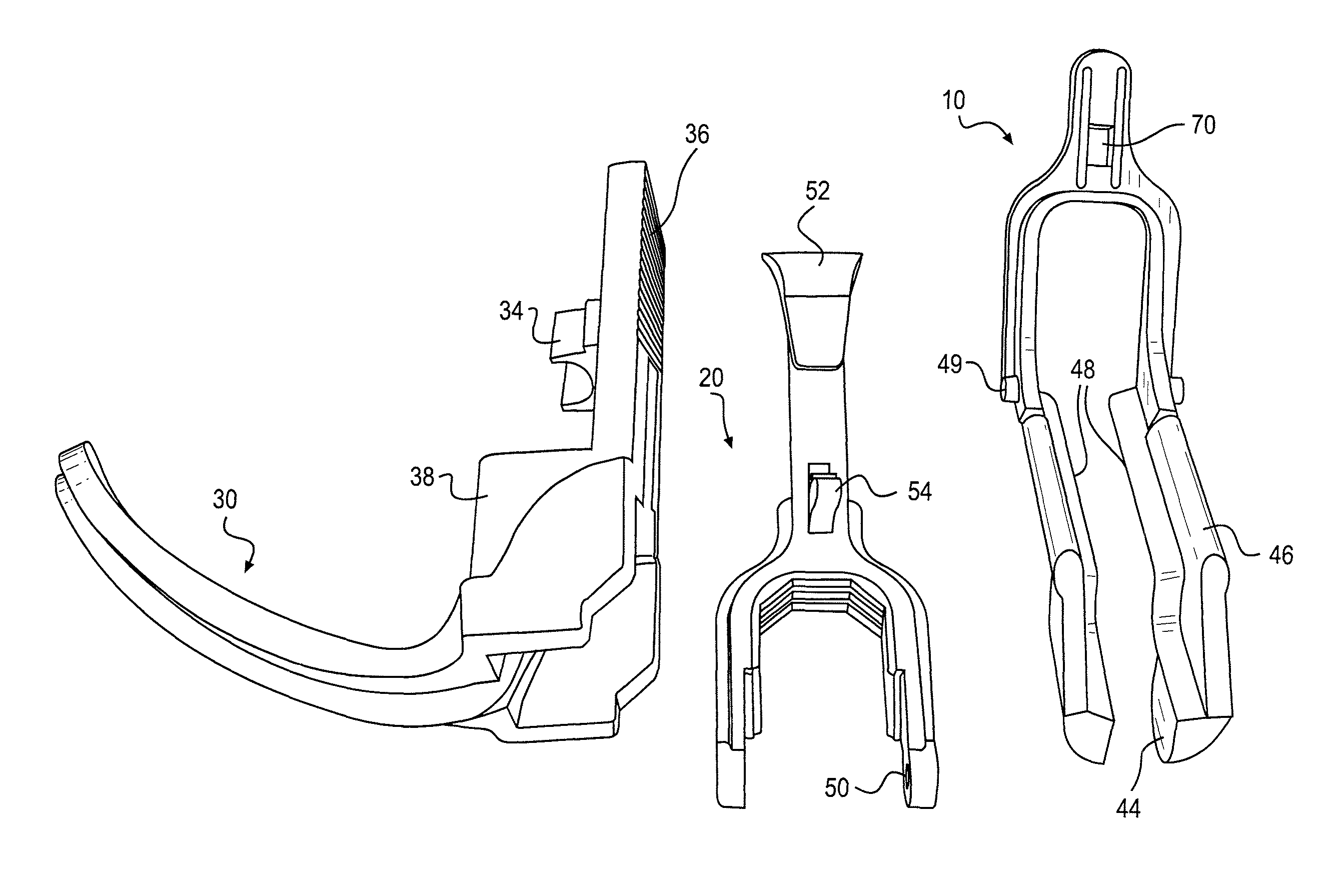
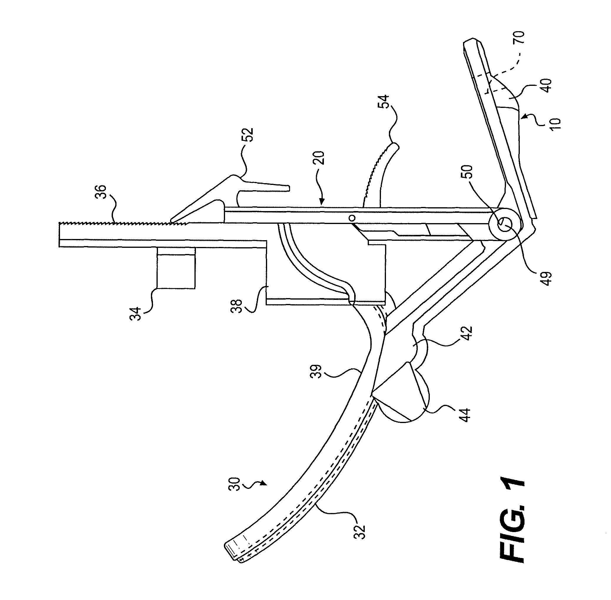
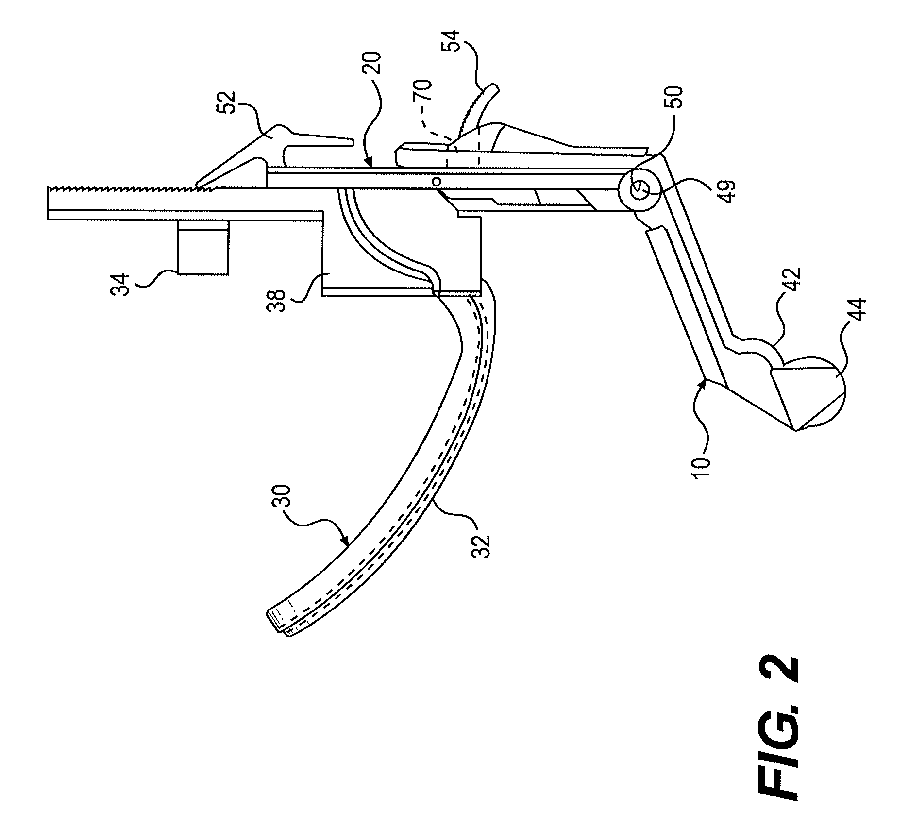
[0052]Referring to FIG. 1, which illustrates the closed position of the preferred embodiment of the present invention, the self-retaining laryngoscope is composed of three components: 1) the palate brace or blade 10, 2) the slider 20, and 3) the tongue blade 30.

[0053]The tongue blade 30 includes the angulated blade 39 with light conduction “rail”32, the light source clip 34, an interface 38, and the teeth 36 for interaction with the slider thumb piece 52 to allow retraction and wider opening of the mouth and airway.

[0054]The configuration of the tongue blade 30 has been shown during clinical trials to require an angulation 39 of the blade. A straight blade does not conform to the natural curve of the airway. The new angle 39 of the present invention in its preferred embodiment was clinically tested for optimization, and was found to be a curve of approximately 60 degrees. It is sized to be either small, medium, or large.

[0055]The narrowing of the width of the tongue blade 30 to 2 ce...


PUM


Abstract

The present invention is a self-retaining laryngoscope composed of a palate brace or blade, a slider, and a tongue blade. The angulated tongue blade puts less force on the blade, reduces trauma, and is not conducive for mechanical failure. The slider interacts with the tongue blade by widening the opening of the mouth, and acts as a bite block. The fenestrated palate blade provides an unobstructed view of the vocal cords during intubation, and allows removal of the laryngoscope over the endotracheal tube without displacing it. The result is a laryngoscope that requires only one hand to use properly, and has superior retraction due to its shape.

Description

CITATION TO PARENT APPLICATION[0001]This is a non-provisional application which claims priority, pursuant to 35 U.S.C. 119, to U.S. provisional application Ser. No. 60 / 828,383, filed 6 Oct. 2006.BACKGROUND OF THE INVENTION[0002]1. Field of the Invention[0003]The present invention relates to medical instruments, and more particularly to an improved laryngoscope.[0004]2. Background Information[0005]The early need to visualize the larynx was for surgical purposes. As a medical student in 1829, Benjamin Guy Babington created a “glottiscope.” One shank held down the tongue while the other was positioned along the palate. Sunlight provided the illumination for a view of the glottis. The glottiscope was later termed the laryngoscope by his contemporary, Thomas Hodgkins. In 1844, surgeon John Avery developed a head-mounted mirror that reflected candlelight onto a mirror housed within a speculum. But it was Manual Garcia (1805-1906), a professor of singing at the Royal Academy of Music in Lo...

Claims


Application Information

Patent Timeline
Patent Type & Authority Patents(United States)
IPC IPC(8): A61B1/32
CPCA61B1/267
Inventor MINSON, MATTHEW
Owner MINSON MATTHEW
Why Eureka
Eureka Blog
Learn More