Image stabilizer and optical instrument therewith

a technology which is applied in the field of image stabilizer and optical instrument therewith, can solve problems such as camera shake, and achieve the effects of reducing the size and cost of image stabilizer and high precision

Inactive Publication Date: 2012-02-07
FUJIFILM CORP
View PDF12 Cites 10 Cited by
  • Summary
  • Abstract
  • Description
  • Claims
  • Application Information

AI Technical Summary

Benefits of technology

[0008]A main object of the present invention is to provide a small image stabilizer by negating the need for guide shafts.
[0011]A camera shake becomes a problem in taking a still image or a moving image. In taking the still image, a shutter button is pressed down while holding a digital still camera with both hands. If the camera shake occurs during the press of the shutter button, the image to be captured is blurred. The camera shake is detected by a shake detector, e.g. an angular velocity sensor. According to detected angular velocity, X-axis and Y-axis target shift amounts of the optical element are determined. The first printed coil and the second printed coil are energized in accordance with the target shift amounts. Upon energization of the first and second printed coils, Lorentz forces that occur between the first printed coil and the first stationary magnet and between the second printed coil and the second stationary magnet shift the optical element holder in the opposite direction of the camera shake, while elastically bending the first and second leaf springs. The shift of the optical element holder counteracts a move of the image formed on the image sensor due to the camera shake, so that a sharp image without a blur is captured. Upon stopping the camera shake, the energization of the first and second printed coils is stopped. In this case, the elasticity of the first and second leaf springs returns the optical element holder to its standard position. In the standard position, the center of the image sensor is aligned with the optical axis.
[0019]According to the present invention, the second printed circuit board or the second drive magnet holds the optical element holder via the pair of first leaf springs. Therefore, obviating the need for a slider for holding the optical element and guide shafts for supporting the slider, which are used in the prior art, achieves reduction of the image stabilizer in size and cost. Elimination of wobble, which has occurred between the guide shaft and a bearing, allows to detect the position of the optical element with high precision.

Problems solved by technology

A camera shake becomes a problem in taking a still image or a moving image.

Method used


Image

  • Image stabilizer and optical instrument therewith
  • Image stabilizer and optical instrument therewith
  • Image stabilizer and optical instrument therewith

Examples


first embodiment

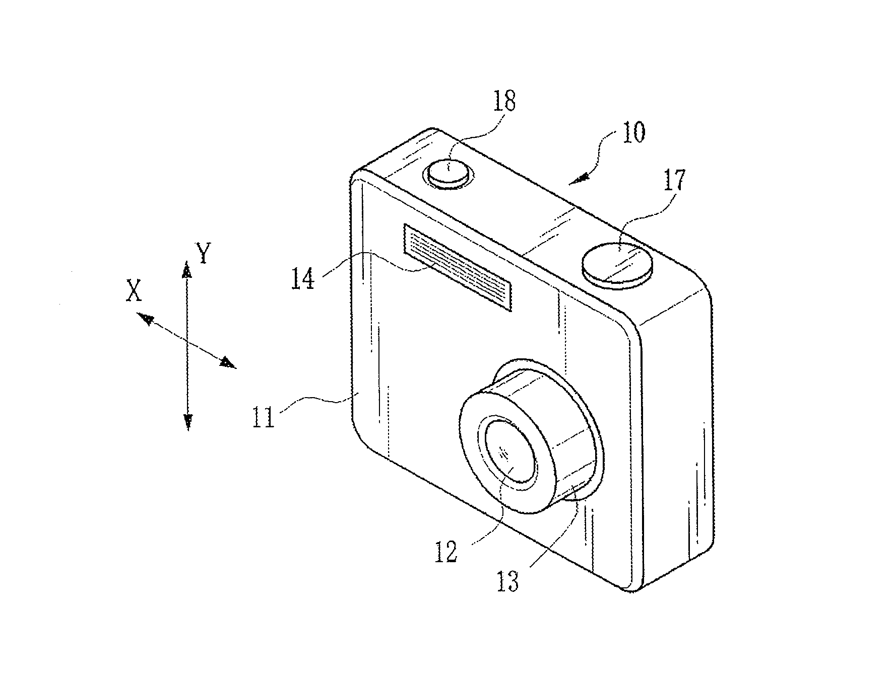
[0030]As shown in FIG. 1, a digital still camera 10 has a lens barrel 13 for containing an optical system 12, a flashlight emitter 14 for applying flashlight to an object and the like in a front face of a camera body 11.

[0031]On a top face of the camera body 11, there are provided an operation dial 17 and a shutter button 18. The operation dial 17 is used for turning the power on and off, and switching an operation mode (among a photographing mode, a playback mode and the like). The shutter button 18 is a two-step push switch, and used for taking an image. Upon turning on a first-step switch SW1 by a half press of the shutter button 18, the digital still camera 10 makes preparation for image taking (exposure setting and focusing). After that, when a second-step switch SW2 is turned on by a full press of the shutter button 18, the digital still camera 10 captures a still image and stores image data on a memory card 26.

[0032]As shown in FIG. 2, a liquid crystal display (LCD) 21, a zoo...

second embodiment

[0073]The VCMs 42 of the first embodiment are of the so-called moving coil type, in which a coil is attached to a movable element, but VCMs of moving magnet type, in which a magnet is attached to the movable element, are available instead. In the following second embodiment, the VCMs of moving magnet type are used. Detailed description of components identical or similar to those of the first embodiment will be omitted.

[0074]In a CCD support mechanism 90 shown in FIG. 8, a first drive magnet 91, instead of the first printed circuit board 71, is attached to the bottom face of the CCD holder 65. Instead of the second printed circuit board 66, a second drive magnet 96 having a magnetized section 92 is used. In front of the first drive magnet 91 and the magnetized section 92, a third printed circuit board 98 having a third printed coil 93a, a third Hall element 93b, a fourth printed coil 94a and a fourth Hall element 94b is disposed. In the camera body 11, the third printed coil 93a and ...


PUM


Abstract

A CCD support mechanism includes a CCD holder for holding a CCD, a first printed circuit board having a first printed coil, a second printed circuit board having a second printed coil, a pair of horizontal leaf springs, and a pair of vertical leaf springs. When a camera shake occurs by hand-held shooting, a VCM composed of the first printed coil and a first stationary magnet shifts the CCD, while bending the horizontal leaf springs, to counteract the camera shake in a Y-axis direction. A VCM composed of the second printed coil and a second stationary magnet shifts the CCD, while bending the vertical leaf springs, to counteract the camera shake in an X-axis direction. Current values of the VCMs are determined by feedback control by using an output signal from a shake detector as a target value and a present position from a position detector as a measurement value.

Description

BACKGROUND OF THE INVENTION[0001]1. Field of the Invention[0002]The present invention relates to an image stabilizer for correcting an image blur due to hand-held shooting, and an optical instrument therewith.[0003]2. Description Related to the Prior Art[0004]Many optical instruments including digital still cameras have an image stabilizer or a shake correction device for correcting an image blur caused by vibration or a camera shake due to hand-held shooting. The image stabilizer is constituted of a shake detector for detecting the camera shake, a holder for movably holding an optical element such as a taking lens or an image sensor, a computing unit, an actuator for shifting the holder in a plane where the optical element is orthogonal to a photography optical axis, and a position detector for detecting the position of the optical element. The computing unit calculates which direction and how much the optical element should be shifted, based on a detection result of the shake dete...

Claims


Application Information

Patent Timeline
Patent Type & Authority Patents(United States)
IPC IPC(8): H04N5/228G03B17/00G02B27/64
CPCG02B27/646G03B5/00H04N5/23248H04N5/23258H04N5/23287G03B2205/0069G03B2205/0038H04N23/68H04N23/6812H04N23/687
Inventor MAKIMOTO, AKIHIROTOKIWA, KENTARO
Owner FUJIFILM CORP
Why Eureka
Try Eureka