Camera body and imaging device equipped with same

a technology of imaging device and camera body, which is applied in the field of camera body and imaging device equipped with same, can solve the problems of consuming a greater amount of electrical power, reducing the space surrounding electronic parts, and increasing so as to achieve the effect of suppressing the increase in the temperature of the imaging device and suppressing the increase in the temperature of the body moun

Active Publication Date: 2011-04-26
PANASONIC CORP
View PDF10 Cites 5 Cited by
  • Summary
  • Abstract
  • Description
  • Claims
  • Application Information

AI Technical Summary

Benefits of technology

[0006]There has long been a need for smaller imaging devices, and with interchangeable lens digital cameras, there is a need to reduce the size of the camera body.
[0007]When the camera body is made smaller, however, this reduces the space surrounding the electronic parts, such as the imaging element or the main circuit board on which the camera controller is mounted, which means that these electronic parts are packed together more densely.
[0011]With this camera body, heat generated by the imaging element is conducted through the intermediate part from the imaging element to the main frame. Since a metal heat radiating member is connected to the intermediate part here, part of the heat conducted to the intermediate part is radiated through the heat radiating member. As a result, there is a reduction in the amount of heat conducted from the imaging element to the main frame, and it is less likely that heat generated by the imaging element will be conducted to the main frame. Consequently, an increase in the temperature of the body mount supported by the main frame can be suppressed.

Problems solved by technology

When the camera body is made smaller, however, this reduces the space surrounding the electronic parts, such as the imaging element or the main circuit board on which the camera controller is mounted, which means that these electronic parts are packed together more densely.
Meanwhile, as image quality rises, the imaging element and the camera controller consume a greater amount of electrical power, so these electrical parts generate more heat.
As a result, the thermal density around the electronic parts rises, and there is the risk that the heat generated by the electronic parts will be conducted to the main frame and other such members, and that the temperature of the members supported by the main frame (such as the body mount) will rise.
In this case, it is possible that the body mount may feel hot to the user's touch.

Method used


Image

  • Camera body and imaging device equipped with same
  • Camera body and imaging device equipped with same
  • Camera body and imaging device equipped with same

Examples


first embodiment

1-1: Overview of Digital Camera

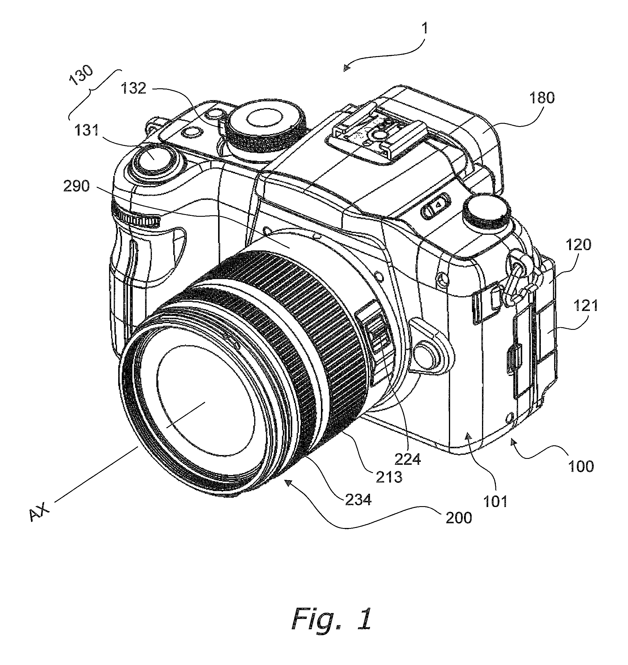
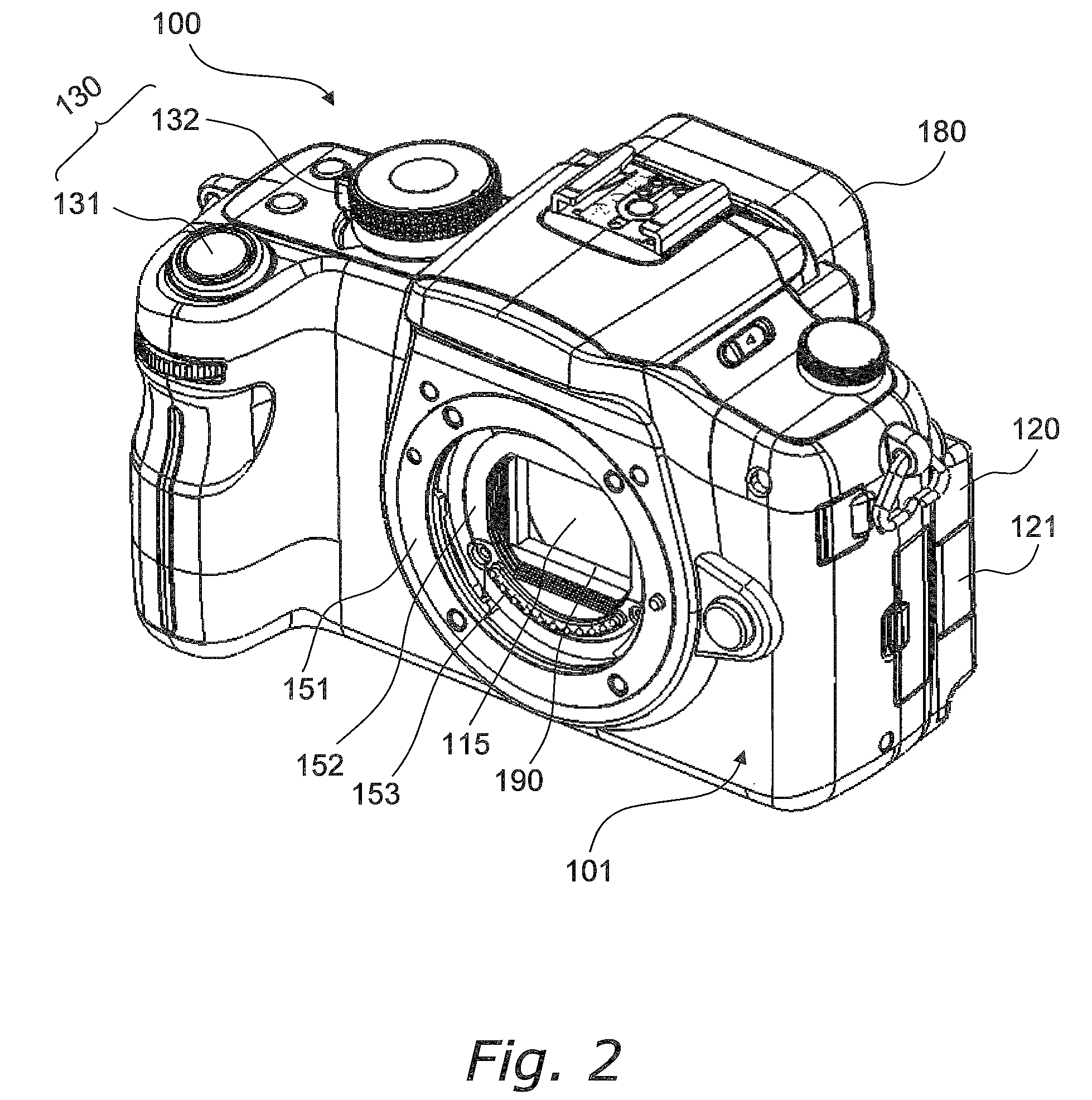
[0028]FIG. 1 is an oblique view of a digital camera 1 according to a first embodiment. FIG. 2 is an oblique view of a camera body 100. FIG. 3 is a function block diagram of the digital camera 1.

[0029]The digital camera 1 is an interchangeable lens digital camera, and includes the camera body 100 and a lens unit 200 that can be mounted to the camera body 100.

[0030]Unlike a single lens reflex camera, the camera body 100 does not have a mirror box device, so the flange back is smaller than with a single lens reflex camera. Also, reducing the size of the flange back makes the camera body 100 smaller. Furthermore, reducing the size of the flange back affords greater latitude in the design of the optical system, so the lens unit 200 can be smaller. The various components will now be described in detail.

[0031]For the sake of this description, the subject side of the digital camera 1 will also be called the front, the vertical upper side will also be called th...

second embodiment

[0123]In the first embodiment above, the heat radiating member 198 is connected to the diaphragm support 116, but the heat radiating member 198 may instead be connected to another member. Here, the description will focus on differences from the camera body 100 of the first embodiment, and portions that are shared will not be described again. Furthermore, members having substantially the same function as in the first embodiment will be numbered the same, and will not be described again in detail.

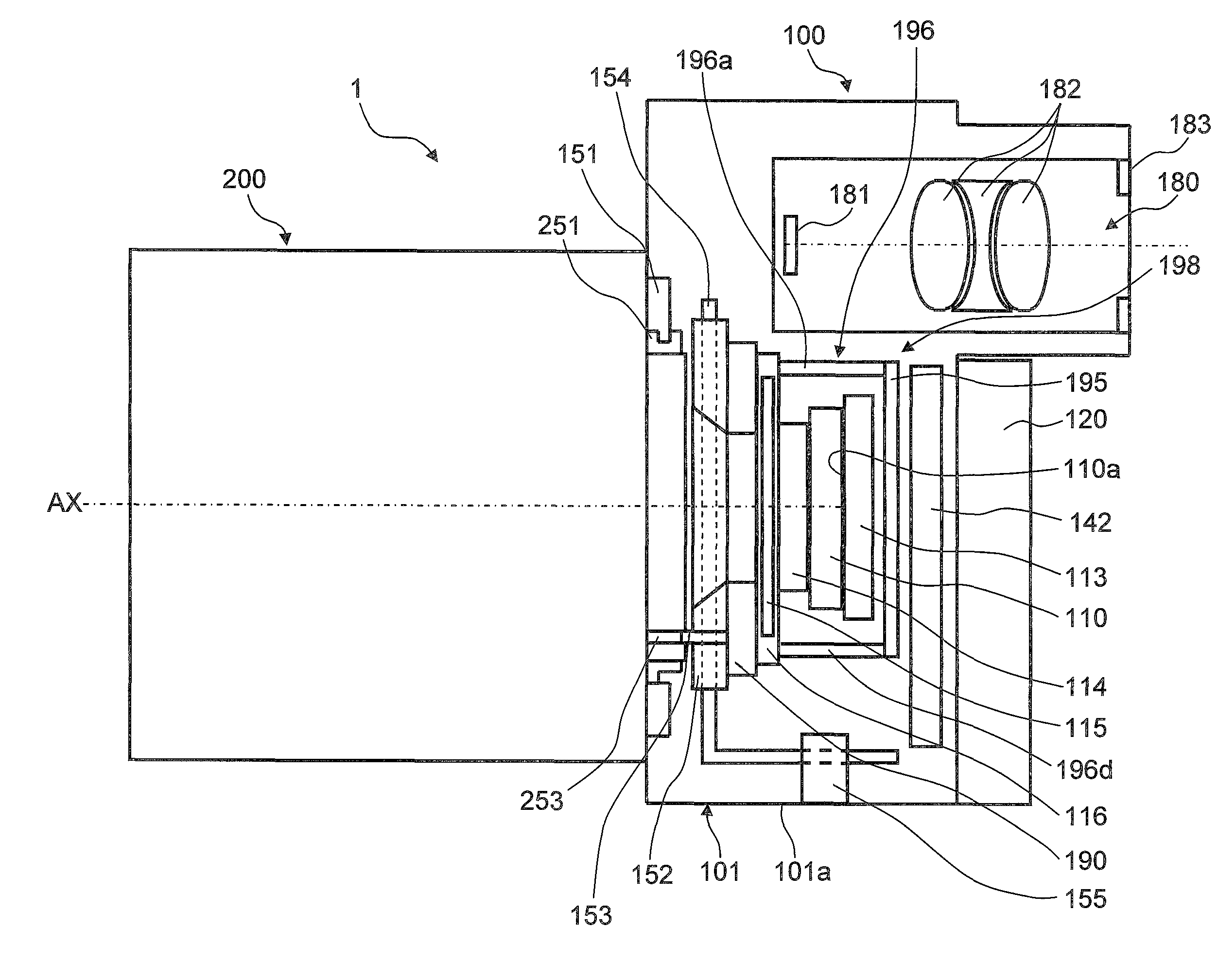
[0124]FIG. 9 is a simplified cross section of a camera body 400 according to the second embodiment. The camera body 400 differs from the camera body 100 in the first embodiment only in that the thermal conductor 196 of the heat radiating member 198 is connected not to the diaphragm support 116, but to the shutter unit 190, and the rest of the configuration is substantially the same as that of the camera body 100.

[0125]The thermal conductor 196 has a first plate 196a disposed above the CMOS im...

third embodiment

[0130]The embodiment described below is also conceivable. The description will focus on differences from the camera body 100 of the first embodiment, and portions that are shared will not be described again. Furthermore, members having substantially the same function as in the first embodiment will be numbered the same, and will not be described again in detail.

[0131]FIG. 10 is a simplified cross section of a camera body 500 according to the third embodiment. The camera body 500 differs from the camera body 100 in the first embodiment only in that the thermal conductor 196 of the heat radiating member 198 is connected not to the diaphragm support 116, but to the body mount contact support 152, and the rest of the configuration is substantially the same as that of the camera body 100.

[0132]The thermal conductor 196 has a first plate 196a disposed above the CMOS image sensor 110, a second plate 196b and a third plate 196c disposed to the sides of the CMOS image sensor 110, and a fourt...


PUM


Abstract

A camera body includes a body mount to which the lens unit can be mounted, a metal main frame supporting the body mount, an imaging element configured to convert an optical image of the subject into image data, an intermediate part disposed along a thermal conduction path formed between the main frame and the imaging element, and a metal heat radiating member connected to the intermediate part.

Description

CROSS-REFERENCE TO RELATED APPLICATIONS[0001]This application claims priority to Japanese Patent Application No. 2008-233191 filed on Sep. 11, 2008. The entire disclosure of Japanese Patent Applications No. 2008-233191 is hereby incorporated herein by reference.BACKGROUND[0002]1. Technical Field[0003]The technical field relates to a camera body to which a lens unit can be mounted, and to an imaging device equipped with this camera body.[0004]2. Description of the Related Art[0005]Interchangeable lens digital cameras are an example of a known imaging device. The camera discussed in Japanese Laid-Open Patent Application 2007-127836, for example, includes a lens unit and a camera body. This camera body has an imaging element such as a CCD (charge coupled device) image sensor, and a mirror box device disposed between the lens unit and the imaging element. The mirror box device guides the light that has passed through the lens unit to either a CCD image sensor or a prism. The light guide...

Claims


Application Information

Patent Timeline
Patent Type & Authority Patents(United States)
IPC IPC(8): G03B17/00G03B17/02G03B17/14H04N5/225H04N5/335H04N5/374H04N101/00
CPCG03B17/14H04N5/2254G03B17/55H04N23/52H04N23/55
Inventor IYODA, MAKOTOINOUE, ATSUSHINAGAOKA, RYUICHI
Owner PANASONIC CORP
Why Eureka
Try Eureka