Device and method for fingerprints supervision

Inactive Publication Date: 2004-02-12
PRECISE BIOMETRICS AB
View PDF6 Cites 7 Cited by
  • Summary
  • Abstract
  • Description
  • Claims
  • Application Information

AI Technical Summary

Problems solved by technology

Optical sensors have the disadvantage of being unwieldy in design, on account of the lens system.
The capacitive silicon sensors are relatively expensive as they require a large silicon area.
This sensor requires a smaller silicon area than the sensors that record a whole fingerprint from a finger that is held still, but on the other hand is

Method used


Image

  • Device and method for fingerprints supervision
  • Device and method for fingerprints supervision
  • Device and method for fingerprints supervision

Examples


Embodiment Construction

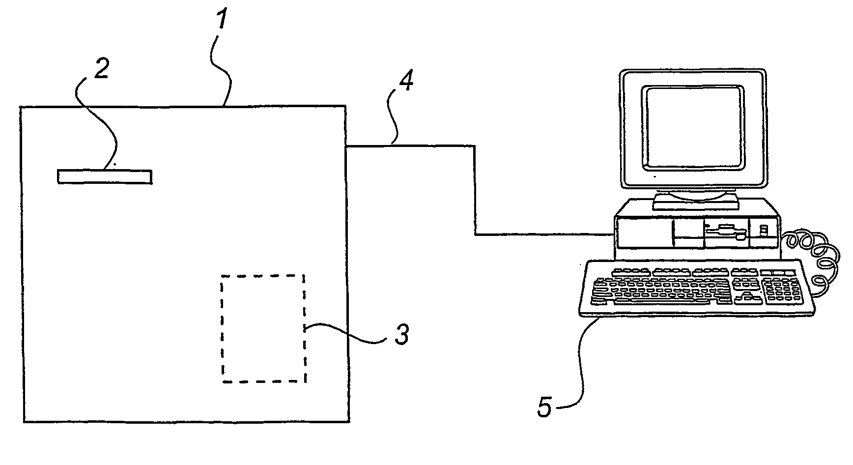
[0045] FIG. 1 shows a device 1 according to the invention for checking fingerprints. The device comprises a long and narrow silicon sensor, which is 1 mm high and 10 mm wide, and a comparison device 3 for comparing an image recorded by the silicon sensor with a reference image which was stored in the device previously. The device has an output 4 via which an output signal can be sent indicating whether the fingerprint conforms with the reference fingerprint. The device is designed as a free-standing unit which is connected to a computer 5 which is made available to the user if the reference image conforms with the fingerprint that is recorded by the silicon sensor.

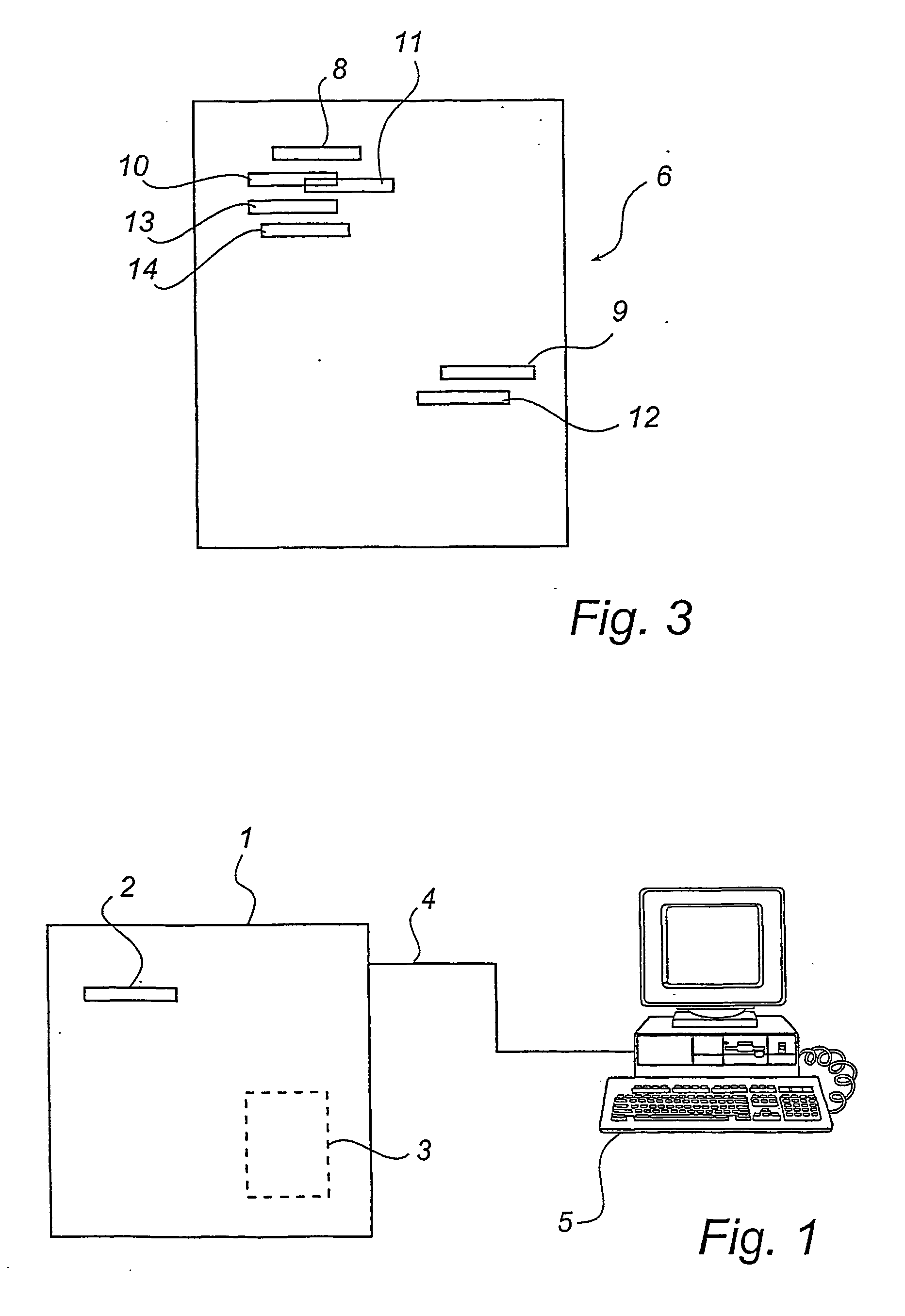
[0046] FIG. 2 shows a reference image 6 of a fingerprint. The black lines 7 correspond to grooves in the fingerprint. The reference image has been recorded by the same sensor 2 as is used for checking the fingerprints.

[0047] FIG. 3 shows schematically the reference image 6 from FIG. 2. The function of the device will now b...


PUM


Abstract

A method and a device for checking fingerprints are described. The method comprises the steps of recording in succession at least two digital images of finger areas and comparing each of the recording images with a reference image that represents at least one previously recorded reference fingerprint from a reference finger areas. The device according to the invention is arranged to carry out the method.

Description

[0001] The present invention relates to a device that is intended to be used in a system for checking fingerprints, which device comprises a sensor which is arranged to record a fingerprint from the first joint of a finger. The invention further relates to a method for checking fingerprints.TECHNICAL BACKGROUND[0002] It has been known from time immemorial that fingerprints can be used to identify people. Initially fingerprints were taken manually by inking the first joint of a finger and pressing this onto a sheet of paper. A pattern of lines was thus printed onto the sheet of paper, where the lines corresponded to the ridges and the spaces between the lines corresponded to the grooves in the skin of the finger. Now fingerprints are taken using sensors that detect the pattern on the skin on the part of the finger that is held against the sensor.[0003] Traditionally, fingerprint technology has been used primarily for the identification of criminals, but in recent years it has also be...

Claims


Application Information

Patent Timeline
IPC IPC(8): G06K9/00
CPCG06K9/00087G06K9/00026G06V40/1335G06V40/1365
Inventor TUFVESSON, PER
Owner PRECISE BIOMETRICS AB
Why Eureka
Try Eureka