Airbag cushion and airbag apparatus

a technology for airbags and airbags, which is applied in the direction of pedestrian/occupant safety arrangements, vehicular safety arrangements, vehicle components, etc., can solve the problems of delay in breaking the tear seam, delay in releasing the tear seam, and the seam remains partly unbroken, etc., to achieve rapid and substantially uniform inflatable effect, easy release and rapid

Inactive Publication Date: 2012-03-06
JOYSON SAFETY SYST JAPAN KK
View PDF30 Cites 30 Cited by
  • Summary
  • Abstract
  • Description
  • Claims
  • Application Information

AI Technical Summary

Benefits of technology

[0009]It is an object of the present invention to provide an airbag cushion which is configured to allow the joint between a distal end portion of a lid member and the airbag cushion by a separable joint member to be released easily and rapidly as a whole, and is able to be inflatable rapidly and substantially uniformly as a whole, and an airbag apparatus having the airbag cushion.

Problems solved by technology

Therefore, it takes time until the entire tear seam is broken.
In this case, the breakage of the tear seam may be delayed, or the tear seam remains partly unbroken and the entire airbag cushion can hardly be inflated uniformly.

Method used


Image

  • Airbag cushion and airbag apparatus
  • Airbag cushion and airbag apparatus
  • Airbag cushion and airbag apparatus

Examples


Embodiment Construction

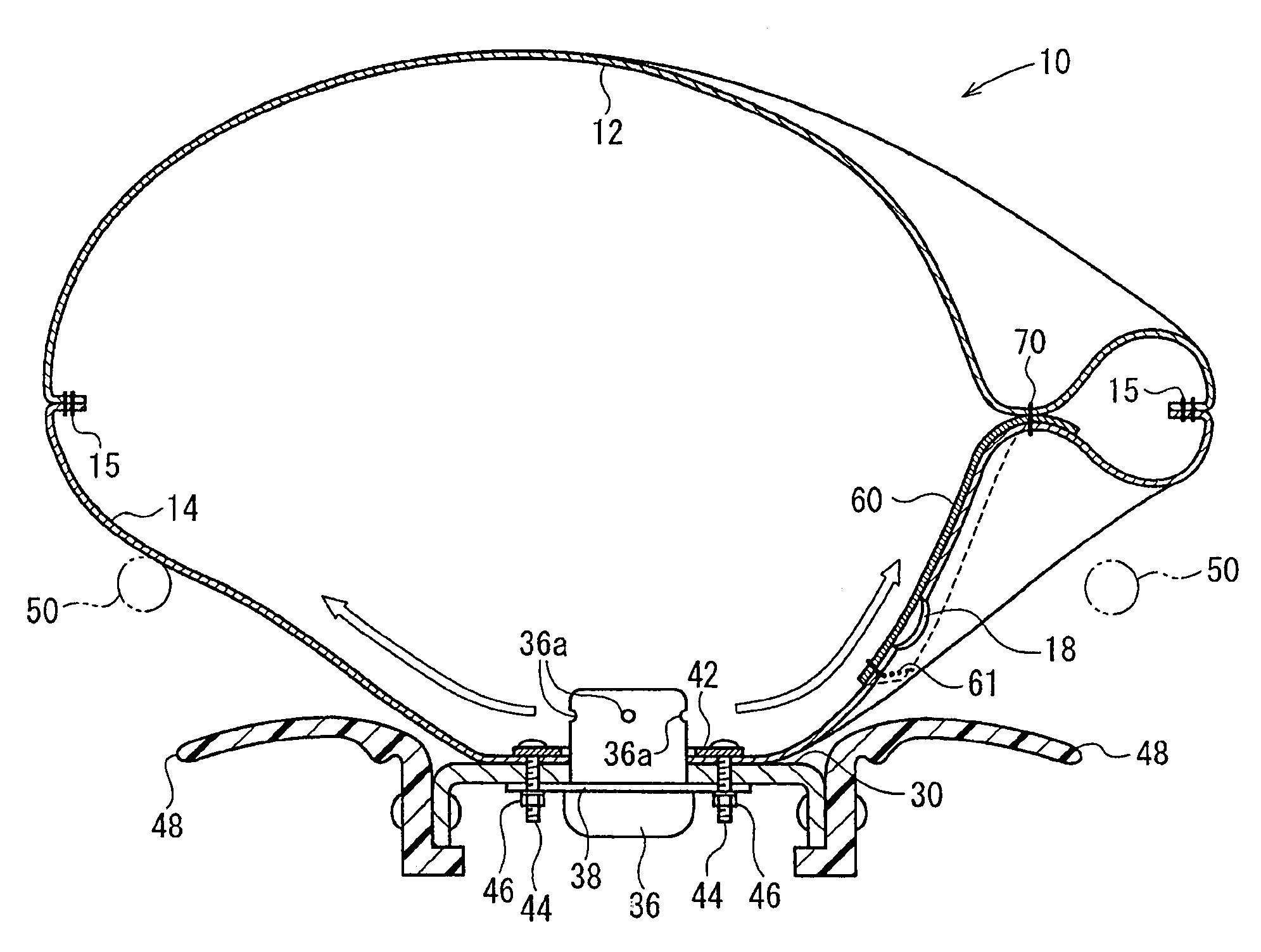
[0034]According to the airbag cushion in the first mode and the airbag apparatus in the ninth mode, since the separable joint member which releasably joins the lid member and the airbag cushion is provided only on a portion where these members are overlapped, and hence the time required for releasing the joint by the separable joint member may be shorter than the case of the airbag cushion disclosed in above-described Japanese Unexamined Patent Application Publication No. 2005-199987 in which the front surface and the rear surface are joined by the tear seam over the entire periphery.

[0035]Also, since a portion other than the overlapped portion with respect to the lid member is not joined by the separable joint member, the airbag cushion can be inflated quickly and substantially uniformly as a whole.

[0036]According to the second mode, since the opposed surfaces of the airbag cushion are joined by the separable joint member at the overlapped portion with respect to the respective lid...


PUM


Abstract

There is provided an airbag cushion which is configured to allow the joint between a distal end portion of a lid member and the airbag cushion by a separable joint member to be released easily and rapidly as a whole, and is able to be inflatable rapidly and substantially uniformly as a whole, and an airbag apparatus having the airbag cushion. A rear panel 14 of an airbag cushion 10 is provided with a vent hole 18 which communicates the interior and the exterior of the airbag cushion 10, and the vent hole 18 is covered with a lid member 60 from the inside of the airbag cushion 10. A distal end portion of the lid member 60 and portions of the front panel 12 and the rear panel 14 of the airbag cushion 10 overlapped with the distal end portion of the lid member 60 are releasably joined by a tear seam 70. The tear seam 70 is broken in 10 to 30 mS after having activated an inflator 36, and started with the inflation of the airbag cushion 10, and the joint among the front panel 12, the rear panel 14 and the distal end portion of the lid member 60 is released.

Description

TECHNICAL FIELD[0001]The present invention relates to an airbag cushion including a vent hole for allowing an occupant to be received softly by the airbag cushion by flowing out gas from the interior of the airbag cushion to the exterior of the airbag cushion, and a lid member configured to cover the vent hole from the inside of the airbag cushion for restraining a flow out of the gas from the vent hole. The present invention also relates to an airbag apparatus having the airbag cushion.BACKGROUND ART[0002]Providing a vent hole on an airbag cushion and allowing gas to flow out from the interior of the airbag cushion through the vent hole when a vehicle occupant or the like plows into the inflated airbag cushion to receive and constrain the vehicle occupant or the like softly by the airbag cushion is publicly known.[0003]In Japanese Unexamined Patent Application Publication No. 2005-199987, an airbag cushion in which the vent hole is covered with the lid member from the inside of the...

Claims


Application Information

Patent Timeline
Patent Type & Authority Patents(United States)
IPC IPC(8): B60R21/239B60R21/203B60R21/205
CPCB60R21/233B60R21/2338B60R21/239B60R2021/23384
Inventor ABE, KAZUHIRO
Owner JOYSON SAFETY SYST JAPAN KK
Why Eureka
Try Eureka