Lamps with replaceable covers
a technology of replaceable covers and lamps, which is applied in the direction of discharge tubes, luminescent screens, vacuum tubes/containers/shields, etc., can solve the problems of waste of dispensable resources, inability to replace other luminosities, and specific luminosities of traditional lamps
- Summary
- Abstract
- Description
- Claims
- Application Information
AI Technical Summary
Problems solved by technology
Method used
Image

Examples
first embodiment
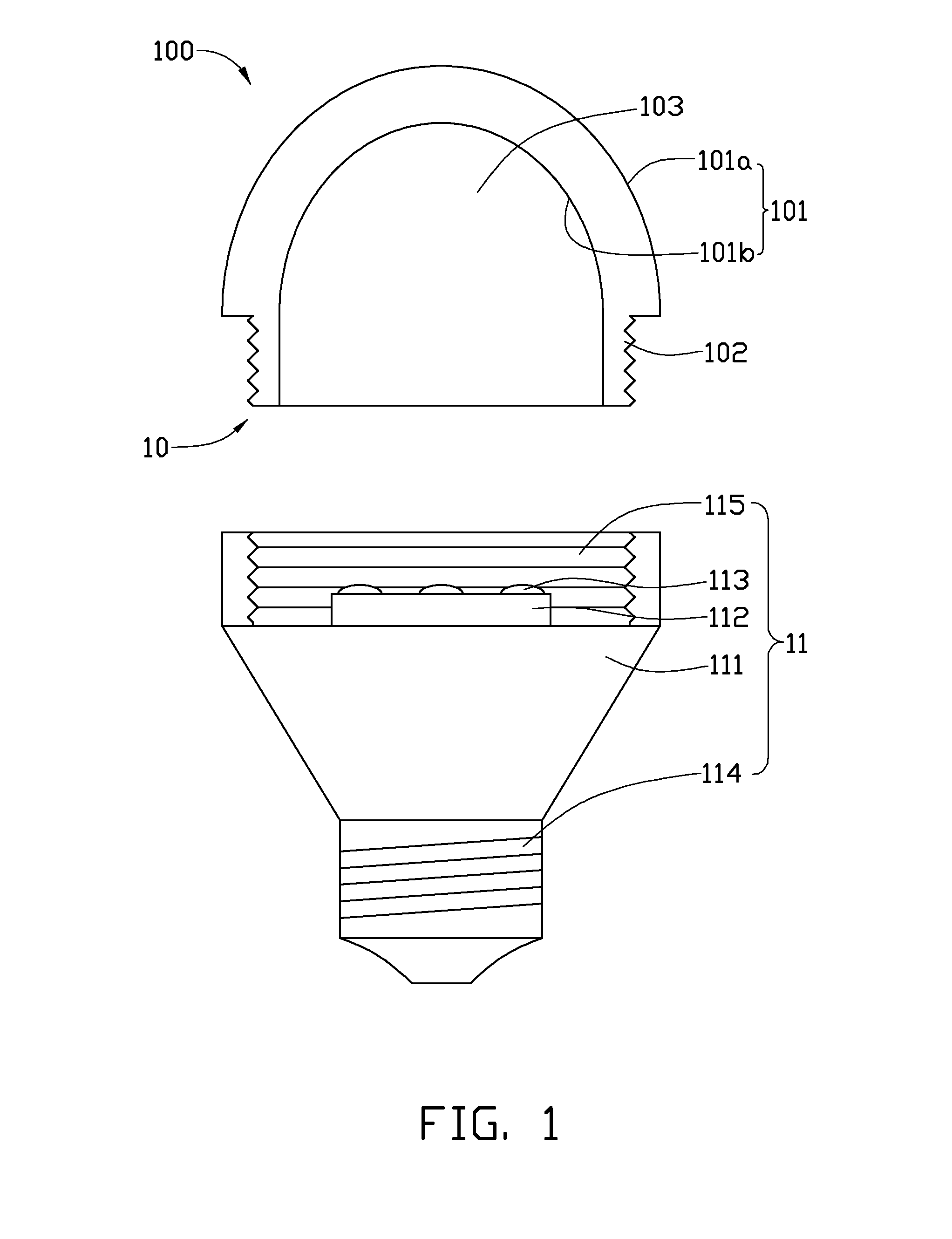
[0018]Referring to FIG. 1, a lamp 100 includes a removable cover 10 and a main body 11.
[0019]The main body 11 includes a lamp housing 111, a printed circuit board (PCB) 112, at least one light emitting element 113, and a threaded base 114. The lamp housing 111 defines a socket 115 with a threaded inner surface (not labeled) and configured for receiving the PCB 112 and the at least one light emitting element 113.
[0020]The lamp housing 111 is made of a heat conductive material such as metal and is electrically insulated from the threaded base 114 and thermally connected with the PCB 112. The PCB 112 is electrically connected to the at least one light emitting element 113 and fixed on the socket 115. The at least one light emitting element 113 can be, for example, a light emitting diode (LED) chip. Heat generated by the at least one light emitting element 113 can be transmitted to the lamp housing 111.
[0021]The removable cover 10 is connected to the lamp housing 111 and configured for...
second embodiment
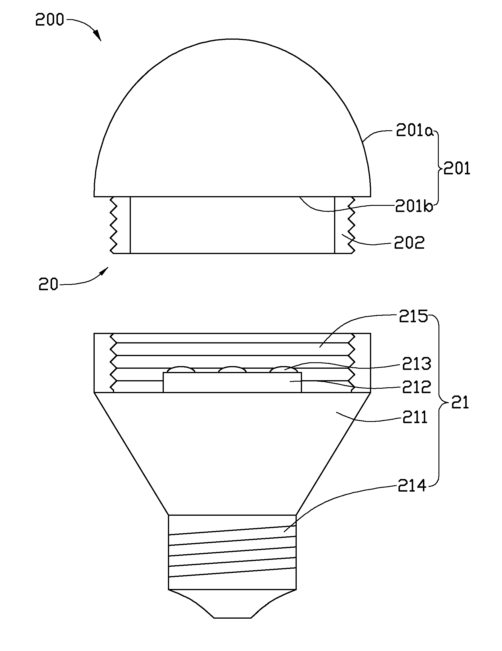
[0030]As shown in FIG. 3, the lamp 200 in accordance with a second embodiment includes a removable cover 20 and a main body 21. The main body 21 includes a lamp housing 211, a printed circuit board (PCB) 212, at least one light emitting element 213, and a threaded base 214. The lamp housing 211 has a socket 215.
[0031]The light emitting element 213 can be a light emitting diode or light emitting diode chip.
[0032]The printed circuit board (PCB) 212 is received in the socket 215. The light emitting element 213 is electrically connected to the printed circuit board (PCB) 212. The inside wall of the socket 215 is threaded.
[0033]The removable cover 20 includes a light-transmission portion 201 and a connection portion 202. The connection portion 202 engages the threads of the socket 215 of the lamp housing 211. Light from the at least one light emitting element 213 is emitted from the light-transmission portion 201.
[0034]The removable cover 20 is a transparent body, and the cover can be re...
PUM
| Property | Measurement | Unit |
|---|---|---|
| light-transmission | aaaaa | aaaaa |
| light emitting surface | aaaaa | aaaaa |
| luminescent | aaaaa | aaaaa |
Abstract
Description
Claims
Application Information
 - R&D
- Intellectual Property
- Life Sciences
- Materials
- Tech Scout
- Unparalleled Data Quality
- Higher Quality Content
- 60% Fewer Hallucinations
Browse by: Latest US Patents, China's latest patents, Technical Efficacy Thesaurus, Application Domain, Technology Topic, Popular Technical Reports.
© 2025 PatSnap. All rights reserved.Legal|Privacy policy|Modern Slavery Act Transparency Statement|Sitemap|About US| Contact US: help@patsnap.com