
Supercharger for an engine
a supercharger and engine technology, applied in the direction of machines/engines, combustion engines, exhaust treatment, etc., can solve the problems of increasing the exhaust flow rate and subsequently increasing the turbine driving force, the structure of the system including the variable-geometry turbocharger is typically complicated, and the engine torque cannot be increased in a broad engine speed range that includes both low and high engine speeds. , to achieve the effect of improving charging performance, improving scavenging performance, and broad operating rang
- Summary
- Abstract
- Description
- Claims
- Application Information
AI Technical Summary
Benefits of technology
Problems solved by technology
Method used
Image

Examples
embodiment 1
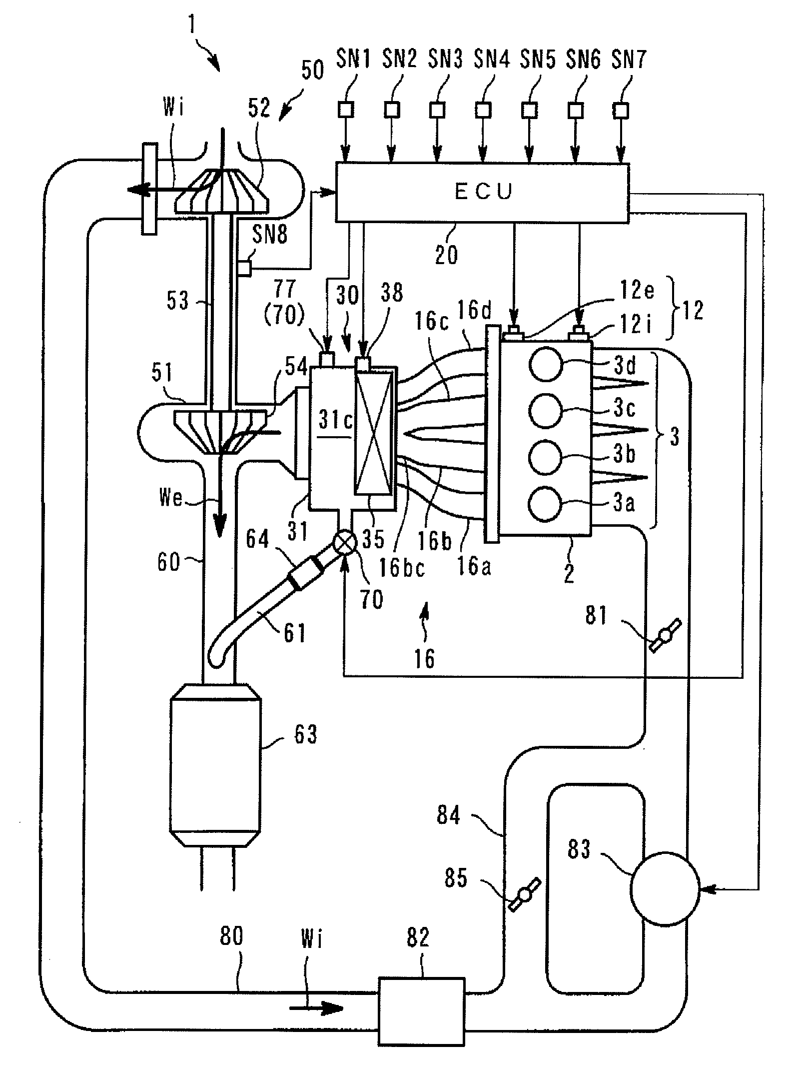
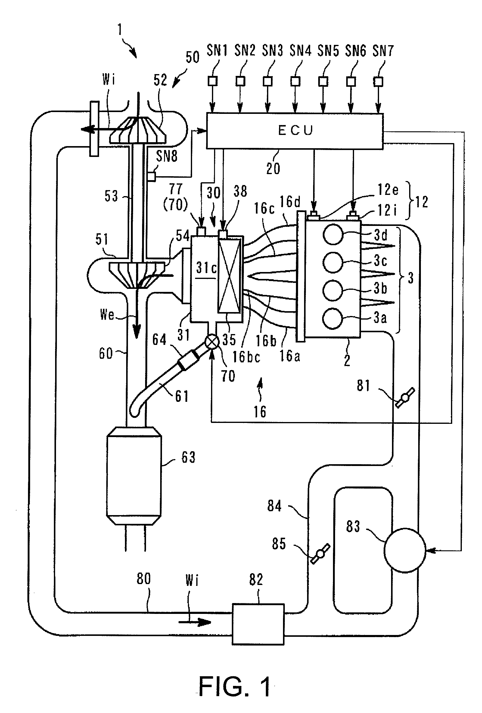
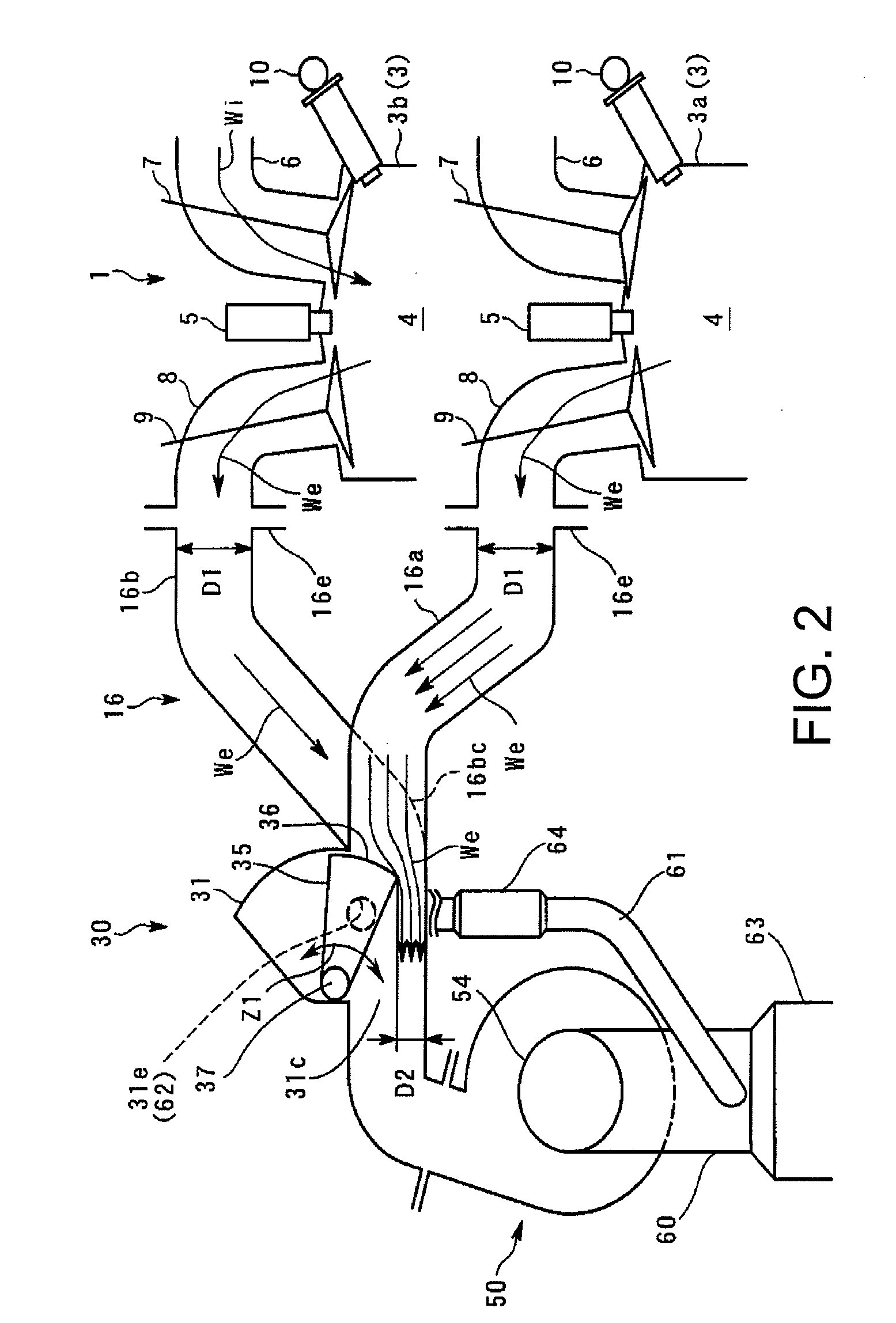
[0082]FIG. 1 is a schematic view showing an engine system with a supercharger according to an embodiment (hereinafter, simply referred to as an “engine”). FIG. 2 is a partial side cross-section of FIG. 1.
[0083]The engine system with the supercharger is provided with an in-line four-cylinder engine 1 of four cycle.
[0084]In this embodiment, the supercharger has a simple configuration using a single turbocharger 50. The turbocharger has characteristics capable of obtaining a high supercharge performance over a wide range from a lower-speed range to a higher-speed range, and generating a high torque throughout the entire range.
[0085]To achieve this, the supercharger primarily provides the following two technical features: (1) improvement in the supercharge performance with dynamic-pressure supercharge; and (2) an independent exhaust choke control using independent exhaust passages and a variable exhaust valve 30. These features will be described in detail later, and first, a configurati...
embodiment 2
[0206]Next, another embodiment of the present invention will be described. The second embodiment is similar to that of the first embodiment in that it has the device configuration shown in FIGS. 1-10, performs the dynamic-pressure supercharge and the independent exhaust choke control, and performs the valve-timing change control. In the first embodiment, the independent exhaust control is only performed in the lower-speed supercharging range A3. However, in this embodiment, the control is also performed in the natural intake range, and in addition, a control to increase the overlapped amount is performed. This takes advantage of the effect of the independent exhaust choke control in which the backward flow of the exhaust gas is controlled by the ejector effect even if the overlapped amount is increased. As a result, an overlap expansion response at the time of an acceleration request can be improved.
[0207]Referring to FIG. 13, the features of this embodiment will be described in det...
embodiment 3
[0216]FIG. 20 is a characteristic plot showing an example setting for an operating range in which a control according to an operating condition according to a third embodiment of the present invention is performed, which has the configuration of FIGS. 1-10. In FIG. 20, the horizontal axis represents an engine speed Ne (rpm), and the vertical axis represents a required torque τ (N-m). The characteristic WOT shows a maximum load torque (engine-fully-open operating range). Supercharge operating ranges R10, R11, R20, and R21 on a higher-load side, and the natural-intake operating ranges R12 and R22 on a lower-load side are set bordering on the characteristic NA.
[0217]Referring to FIG. 20, in this embodiment, among the operating ranges R10-R22, an independent exhaust choking mode is performed in the supercharge operating ranges R10 and R11 on the lower-speed side, and the natural-intake operating range R12. In the independent exhaust choking mode, ECU 20 as a variable exhaust valve contr...
PUM
 Abstract
Description
Claims
Application Information