Method and system for activating catalyst of hybrid vehicle

a technology of hybrid vehicles and catalysts, which is applied in the direction of hybrid vehicles, machines/engines, transportation and packaging, etc., can solve the problems of shortening the time for activating catalysts, affecting the efficiency of engine heating and activation, and generating vibration in the engine. , to achieve the effect of efficient heating and activation, increasing engine torque and reducing the number of times

Active Publication Date: 2016-05-31
HYUNDAI MOTOR CO LTD
View PDF8 Cites 0 Cited by
  • Summary
  • Abstract
  • Description
  • Claims
  • Application Information

AI Technical Summary

Benefits of technology

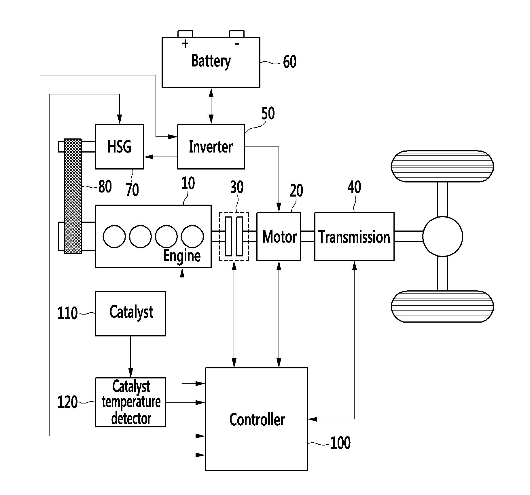
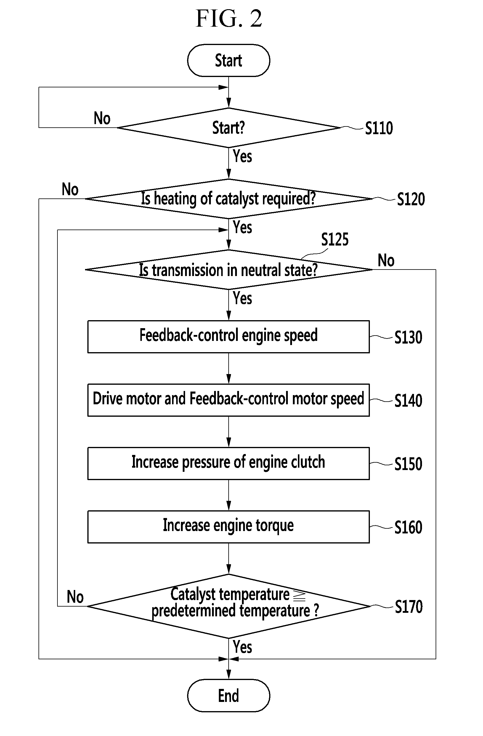
[0010]In an exemplary embodiment, a method of activating a catalyst of a hybrid vehicle may include: increasing torque of an engine by controlling a slip of an engine clutch disposed between the engine and a motor of the hybrid vehicle; determining whether a temperature of the catalyst of the hybrid vehicle reaches a predetermined temperature; and controlling the slip of the engine clutch when the temperature of the catalyst is less than the predetermined temperature.
[0014]According to various exemplary embodiments of the present invention, when the transmission of the hybrid vehicle is in a neutral position, the speed of the motor may be maintained at a predetermined speed, and the engine torque may be increased through the slip of the engine clutch. Consequently, the catalyst of the hybrid vehicle may be efficiently heated and activated.

Problems solved by technology

However, in this process, vibration may be generated in the engine when the ignition angle is excessively retarded.
Particularly, since the conventional system has a structure in which the engine and a power output shaft are physically coupled with each other and the vibration of the engine may be easily transferred to a driver and output demand torque of the driver together with the engine, the ignition angle may be limited in use for the conventional system.
As such, shortening a time for activating the catalyst may not be obtained by increasing the exhaust temperature in the initial stage.
However, as the additional torque is generated in the engine, vibration, noise, and the like may be undesirably generated.

Method used


Image

  • Method and system for activating catalyst of hybrid vehicle
  • Method and system for activating catalyst of hybrid vehicle
  • Method and system for activating catalyst of hybrid vehicle

Examples


Embodiment Construction

[0026]The present invention will be described more fully hereinafter with reference to the accompanying drawings, in which exemplary embodiments of the invention are shown. As those skilled in the art would realize, the described embodiments may be modified in various different ways, all without departing from the spirit or scope of the present invention.

[0027]In the specification, unless explicitly described to the contrary, the word “comprise” and variations such as “comprises” or “comprising,” will be understood to imply the inclusion of stated elements but not the exclusion of any other elements. Like reference numerals designate like elements throughout the specification.

[0028]In addition, it is understood that the term “vehicle” or “vehicular” or other similar term as used herein is inclusive of motor vehicles in general such as passenger automobiles including sports utility vehicles (SUV), buses, trucks, various commercial vehicles, watercraft including a variety of boats and...


PUM


Abstract

A method and a system for activating a catalyst of a hybrid vehicle are provided. In particular, the system and the method maintain a speed of a motor to be a predetermined speed when a transmission of the hybrid vehicle is in a neutral state and heat and activate the catalyst by increasing an engine torque through a slip of an engine clutch. The method includes increasing, by a controller, torque of an engine by controlling a slip of an engine clutch disposed between the engine and a motor of the hybrid vehicle. The controller determines whether a temperature of the catalyst of the hybrid vehicle reaches a predetermined temperature and feedback-controls the slip of the engine clutch when the temperature of the catalyst is less than the predetermined temperature.

Description

CROSS-REFERENCE TO RELATED APPLICATION[0001]This application claims priority to and the benefit of Korean Patent Application No. 10-2014-0067626 filed in the Korean Intellectual Property Office on Jun. 3, 2014, the entire contents of which are incorporated herein by reference.TECHNICAL FIELD[0002]The present invention relates to a method and a system for activating a catalyst of a hybrid vehicle. The method and the system for activating a catalyst of a hybrid vehicle, in particular, may control a speed of a motor to be maintained at a predetermined speed while a transmission is in a neutral position, and thus the catalyst may be heated and activated by increasing an engine torque through a slip of an engine clutch.BACKGROUND[0003]Generally, a hybrid vehicle refers to a vehicle in which a motor of an electric vehicle is applied to a conventional internal combustion engine, or a combination of two or more driving sources such as a combination of an internal combustion engine and a fue...

Claims


Application Information

Patent Timeline
Patent Type & Authority Patents(United States)
IPC IPC(8): B60W10/00F01N3/00F02D3/00F01N3/20B60W10/02B60W10/06B60W10/08
CPCF01N3/2006B60W10/02B60W10/06B60W10/08B60W2510/30B60W2710/025B60W2710/0666B60W2710/08B60W2710/30Y10S903/93B60K6/48B60K2006/4825B60W20/15Y02T10/40Y02T10/62B60W20/00F01N3/08
Inventor KIM, SANG JOON
Owner HYUNDAI MOTOR CO LTD
Why Eureka
Try Eureka