Vehicle headlamp including control to reduce illuminance of additional light distribution pattern and method of controlling the same

a technology of headlamps and control points, which is applied in the direction of lighting and heating equipment, transportation and packaging, and support devices for lighting, etc., can solve the problems of increasing glare light to the driver increasing the illuminance of the additional light distribution pattern, and increasing the glare of the front running vehicle. , to achieve the effect of reducing glare, reducing illuminance of the additional light distribution pattern, and ensuring visibility of the driver

Inactive Publication Date: 2012-04-17
KOITO MFG CO LTD
View PDF12 Cites 8 Cited by
  • Summary
  • Abstract
  • Description
  • Claims
  • Application Information

AI Technical Summary

Benefits of technology

[0011]Accordingly, illustrative aspects of the present invention provide a vehicle headlamp that can secure visibility of a driver and reduce glare caused to a front running vehicle.
[0012]According to an exemplary embodiment of the present invention, a vehicle headlamp is provided. The vehicle headlamp comprises a light source which is configured to form an additional light distribution pattern which is formed above a cut-off line of a low-beam mode light distribution pattern; a vehicle detection device which is configured to detect a presence of a front running vehicle; a road position detection device which is configured to detect an existing area of a road ahead; and a control unit which is configured to acquire information from the vehicle detection device and the road position detection device and, when the existing area includes a non-detectable area which is outside of a detectable area of the vehicle detection device, the control unit controls the light source to reduce an illuminance of the additional light distribution pattern.
[0013]According to another exemplary embodiment of the present invention, there is provided a method of controlling a vehicle headlamp. The method includes reducing an illuminance of an additional light distribution pattern which is formed above a cut-off line of a low-beam mode light distribution pattern, when an existing area of a road ahead includes an area where a front running vehicle cannot be detected.

Problems solved by technology

Even though the high-beam mode is superior in visibility compared with the low-beam mode, there is a disadvantage in that the high-beam mode causes more glare light to a driver of a front running vehicle.
Accordingly, there is a disadvantage with the related art control technique in that a driver of the front running vehicle may falsely recognize that a following vehicle wants to pass.
However, there is a disadvantage in that when the following vehicle comes up on and encounters a front running vehicle before passing through a bent area of the curved road, the front running vehicle comes to be illuminated in the high-beam mode, causing increased glare to the front running vehicle.
In addition, even if the illumination state of the headlamp is switched based on information from a vehicle detection means instead of maintaining the illumination state of the headlamp, there is a disadvantages in that the front running vehicle may be already illuminated in the high-beam mode at a point of time when the front running vehicle is detected in front of the curved road, causing increased glare to the front running vehicle.

Method used


Image

  • Vehicle headlamp including control to reduce illuminance of additional light distribution pattern and method of controlling the same
  • Vehicle headlamp including control to reduce illuminance of additional light distribution pattern and method of controlling the same
  • Vehicle headlamp including control to reduce illuminance of additional light distribution pattern and method of controlling the same

Examples


Embodiment Construction

[0022]Exemplary embodiments of the present invention will be now described with reference to the drawings.

[0023]The same or equivalent elements, members, and processes shown in the drawings are designated by the same reference numerals and repeated description thereof will be omitted.

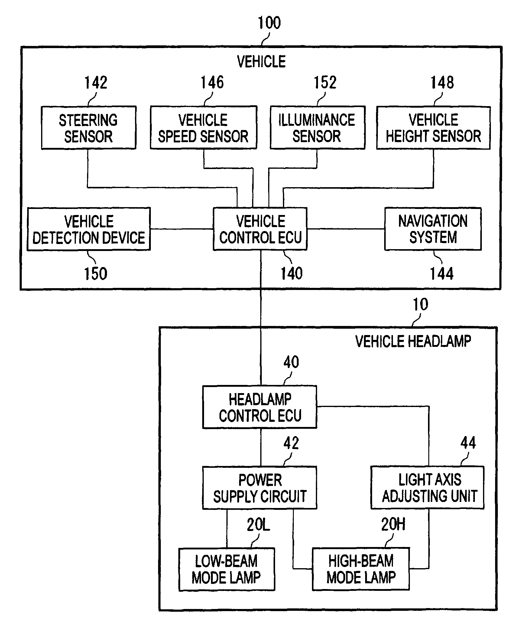
[0024]In a vehicle headlamp according to an exemplary embodiment of the present invention, when an existing area of a road ahead includes an area where a vehicle ahead cannot be detected, an illuminance of an additional light distribution pattern which includes an upper area from a cut-off line of a low-beam mode light distribution pattern is reduced.

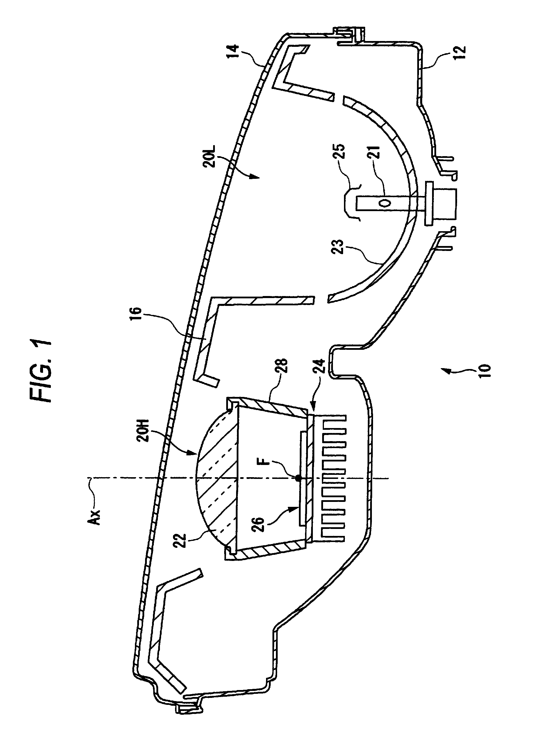
[0025]FIG. 1 is a horizontal sectional view schematically illustrating the vehicle headlamp according to an exemplary embodiment of the present invention.

[0026]The vehicle headlamp 10 according to accommodates a low-beam mode lamp 20L and a high-beam mode lamp 20H in an interior of a lamp housing which is formed by a lamp body 12 and a translucent cover 14....


PUM


Abstract

A vehicle headlamp is provided. The vehicle headlamp includes a light source which is configured to form an additional light distribution pattern which is formed above a cut-off line of a low-beam mode light distribution pattern; a vehicle detection device which is configured to detect a presence of a front running vehicle; a road position detection device which is configured to detect an existing area of a road ahead; and a control unit. The control unit acquires information from the vehicle detection device and the road position detection device and, when the existing area includes a non-detectable area which is outside of a detectable area of the vehicle detection device, controls the light source to reduce an illuminance of the additional light distribution pattern.

Description

[0001]This application claims priority from Japanese Patent Application No. 2008-062677, filed on Mar. 12, 2008, the entire contents of which are hereby incorporated by reference.BACKGROUND OF THE INVENTION[0002]1. Technical Field[0003]Devices, apparatuses, and methods consistent with the present disclosure relate to vehicle headlamps and, more particularly, to vehicle headlamps which control illuminance.[0004]2. Related Art[0005]In general, a vehicle headlamp provided on a vehicle can switch between a low-beam mode and a high-beam mode. The low-beam mode illuminates a place in the vicinity of a front running vehicle with a certain illuminance in order not to cause glare light to the front running vehicle. The front running vehicle includes an oncoming vehicle and / or a leading vehicle which travels in front of and in the same direction as the vehicle. The low-beam mode is mainly used when the vehicle runs in an urban district. On the other hand, the high-beam mode illuminates the fr...

Claims


Application Information

Patent Timeline
Patent Type & Authority Patents(United States)
IPC IPC(8): B60Q1/16
CPCB60Q1/143B60Q2300/054B60Q2300/056B60Q2300/112B60Q2300/122B60Q2300/322B60Q2300/336B60Q2300/42
Inventor MOCHIZUKI, KIYOTAKATATARA, NAOKI
Owner KOITO MFG CO LTD
Why Eureka
Try Eureka