
Orthodontic bracket system and method

a bracket system and orthodontic technology, applied in dental surgery, dental tools, medical science, etc., can solve the problems of discomfort associated with the pressure needed to fasten the ligature tie, the risk of injury to the patient or the operator,

Inactive Publication Date: 2012-04-17
SMS OPCO LLC A DELAWARE LLC
View PDF32 Cites 6 Cited by
  • Summary
  • Abstract
  • Description
  • Claims
  • Application Information

AI Technical Summary

Benefits of technology

This approach reduces the time and risk associated with orthodontic adjustments, enhances patient comfort, and improves efficiency by allowing smooth archwire movement with reduced friction, while enabling flexible archwire configurations as needed during treatment.

Problems solved by technology

Furthermore, because instruments (often sharp instruments) must be used to fasten / unfasten ligature ties or self-ligating clips, these procedures often involve some risk of injury to the patient or operator.
Another disadvantage of traditional open faced orthodontic brackets is the discomfort associated with the pressure that is needed to fasten a ligature tie or open / close a self-ligating clip / door.

Method used


Image

  • Orthodontic bracket system and method
  • Orthodontic bracket system and method
  • Orthodontic bracket system and method

Examples


Embodiment Construction

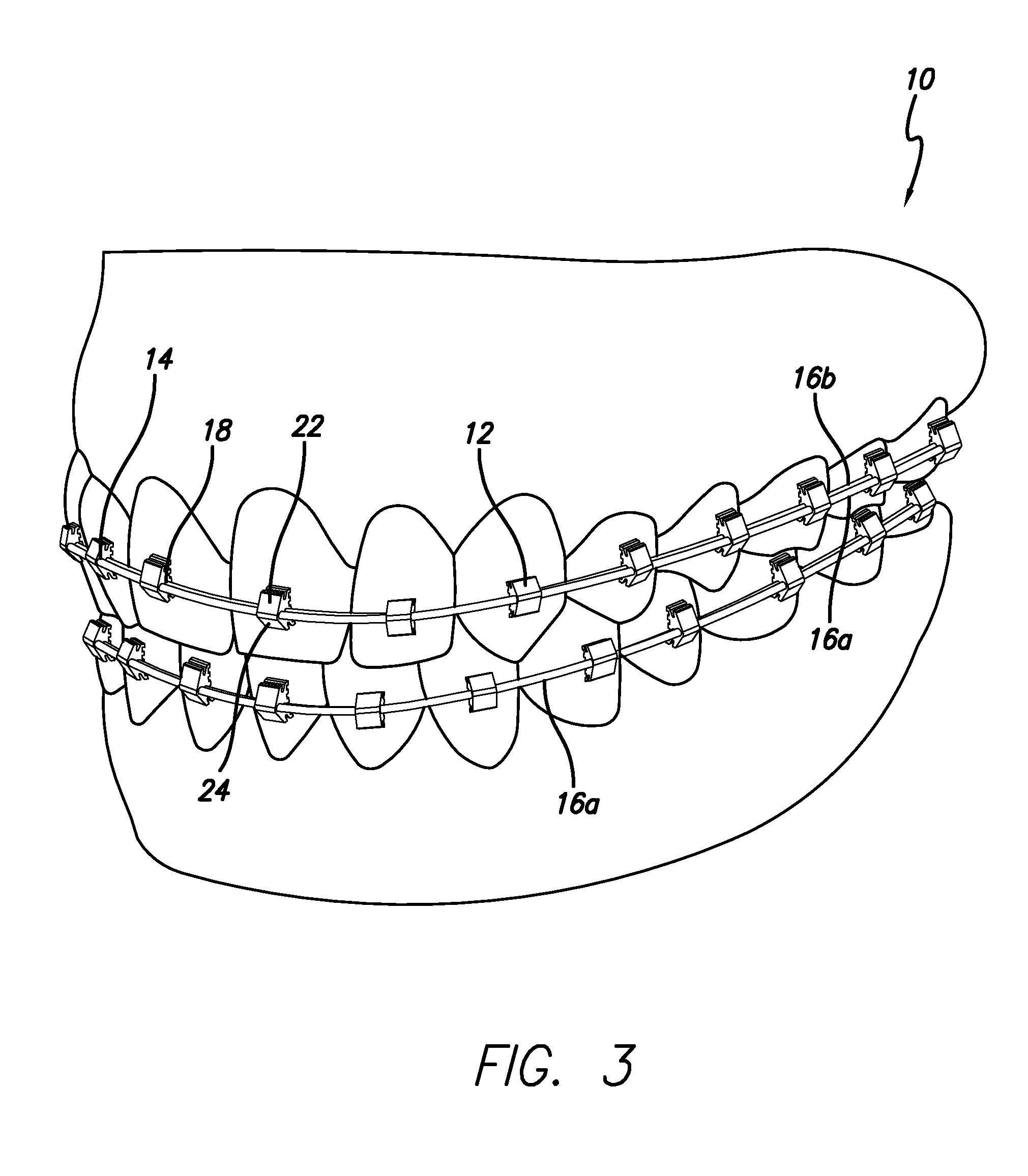
[0022]As shown in the drawings, for purposes of illustration, a preferred embodiment of an orthodontic bracket system 10 is shown and described. It will be appreciated that terms such as “front,”“back,”“top,”“bottom,”“side,”“up,”“down,” and “below” used herein are merely for ease of description and refer to the orientation of the components as shown in the figures. It should be understood that any orientation of the system 10, and the components thereof described herein is within the scope of the present invention.

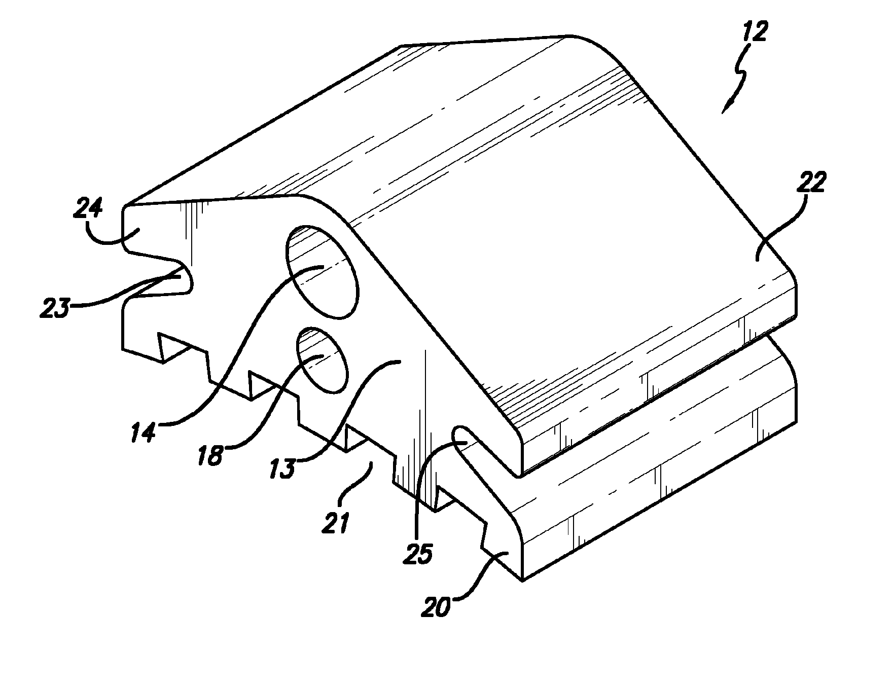
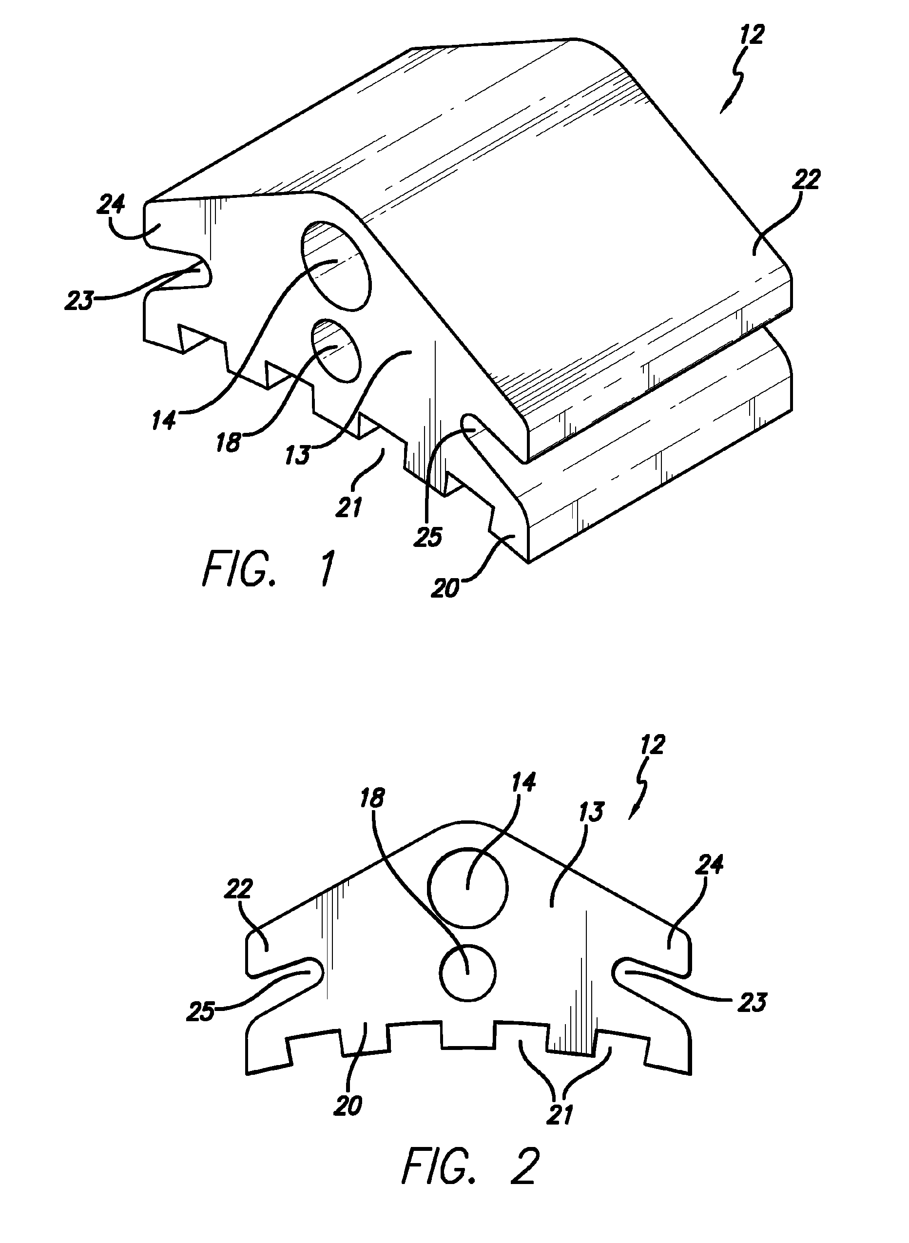
[0023]Referring now to the drawings, wherein the illustrations are for purposes of illustrating the present invention and not for purposes of limiting the same, FIGS. 1-3 show a bracket 12 for use in an orthodontic bracket system 10. As shown in FIG. 1, the bracket 12 includes a main body portion 13 that has a main tunnel, tube or lumen 14 extending horizontally or transversely therethrough and is generally parallel to the occlusal surfaces of the teeth when secured to a t...


PUM


Abstract

Disclosed herein is an orthodontic bracket system for correcting the teeth in an arch that includes molars, premolars, canines, lateral incisors and central incisors. The system includes a plurality of brackets that each include a main body portion having first and second tunnels extending transversely therethrough. Each bracket is bonded to the facial surface of a tooth in the arch. The first and second tunnels of each bracket extend approximately parallel to the facial surface of the tooth to which the bracket is bonded. The system further includes a first archwire extending through the first tunnels in each of the brackets.

Description

FIELD OF THE INVENTION[0001]The present invention relates generally to orthodontic bracket systems, more particularly, to orthodontic bracket systems for limited orthodontic treatment where all brackets include archwire tunnels.BACKGROUND OF THE INVENTION[0002]Existing bracket systems involve an open faced bracket slot as the primary slot that receives an orthodontic archwire. The archwire is placed into the open faced bracket slots and some sort of tie, door or clip is used to close the slot and hold the archwire in the slot. Existing orthodontic bracket systems that include an open faced archwire slot for archwires demand that time be taken by the operator to fasten / ligate / secure the archwire into each open slot using the ligature tie or self-ligating clip. Existing orthodontic bracket systems contain open faced bracket slots because most traditional orthodontic treatment involves the use of stainless steel wires that must be engaged in the open slot and then secured with a ligatu...

Claims


Application Information

Patent Timeline
Patent Type & Authority Patents(United States)
IPC IPC(8): A61C3/00
CPCA61C7/143A61C7/282
Inventor SWAIN, RYAN B.
Owner SMS OPCO LLC A DELAWARE LLC
Learn More