Medical device and method to correct deformity

a technology of medical devices and deformations, applied in the field of medical devices and methods for correcting skeletal deformations, can solve problems such as degeneration of discs, nerve or spinal cord damage, structural instabilities,

Active Publication Date: 2012-04-24
K2M
View PDF351 Cites 92 Cited by
  • Summary
  • Abstract
  • Description
  • Claims
  • Application Information

AI Technical Summary

Benefits of technology

[0013]In accordance with yet another embodiment, a system for correcting a spinal deformity comprises an elongate rod and a plurality of adjustment members coupled to the rod and spaced apart along the rod. The system further comprises a plurality of flexible force-directing members attached to the adjustment member and adapted to be drawn toward the rod by the adjustment member. The system further comprises a plurality of implants. The implants are each configured to connect to a vertebra of a spine and to be a force directing member, allowing a plurality of vertebrae to each be drawn by a said force directing member and a said adjustment member toward the rod.

Problems solved by technology

Certain spine conditions, defects, deformities (e.g., scoliosis) as well as injuries may lead to structural instabilities, nerve or spinal cord damage, pain or other manifestations.
For example, back pain is frequently caused by repetitive and / or high stress loads on or increased motion around certain boney or soft tissue structures.
The natural course of aging leads to degeneration of the disc, loss of disc height, and instability of the spine among other structural manifestations at or around the spine.
The facet joints may develop pain due to arthritic changes caused by increased loads.
Furthermore, osteophytes in the neural foramina and thickening of spinal ligaments can lead to spinal stenosis, or impingement of nerve roots in the spinal canal or neural foramina.
The correction force in this device and in similar devices is a distraction force that may have several drawbacks including possible spinal cord damage, as well as the high loading on the upper and lower attachment sites.

Method used


Image

  • Medical device and method to correct deformity
  • Medical device and method to correct deformity
  • Medical device and method to correct deformity

Examples


Embodiment Construction

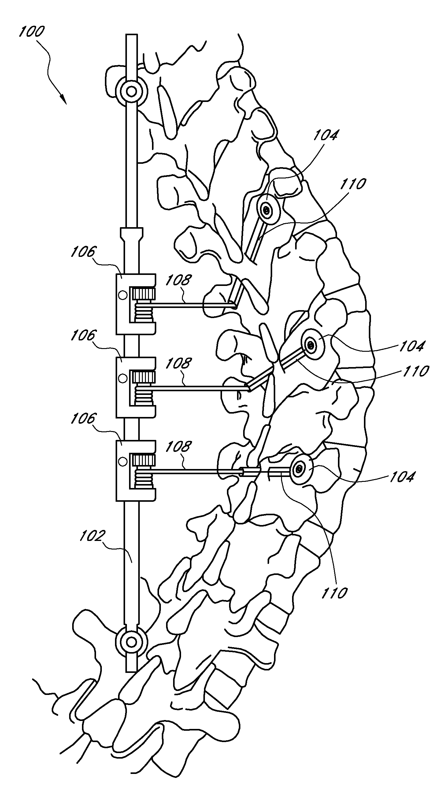
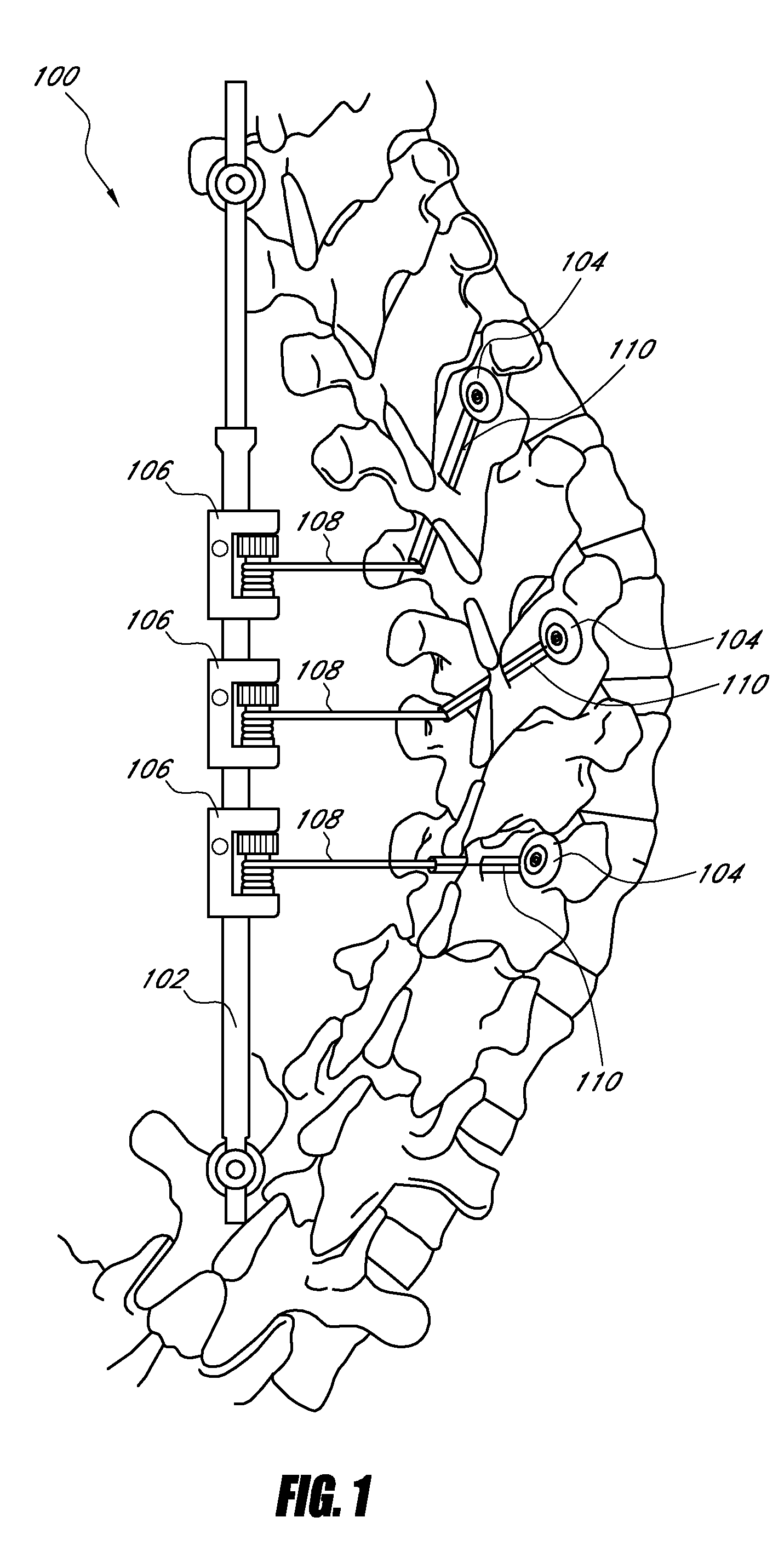
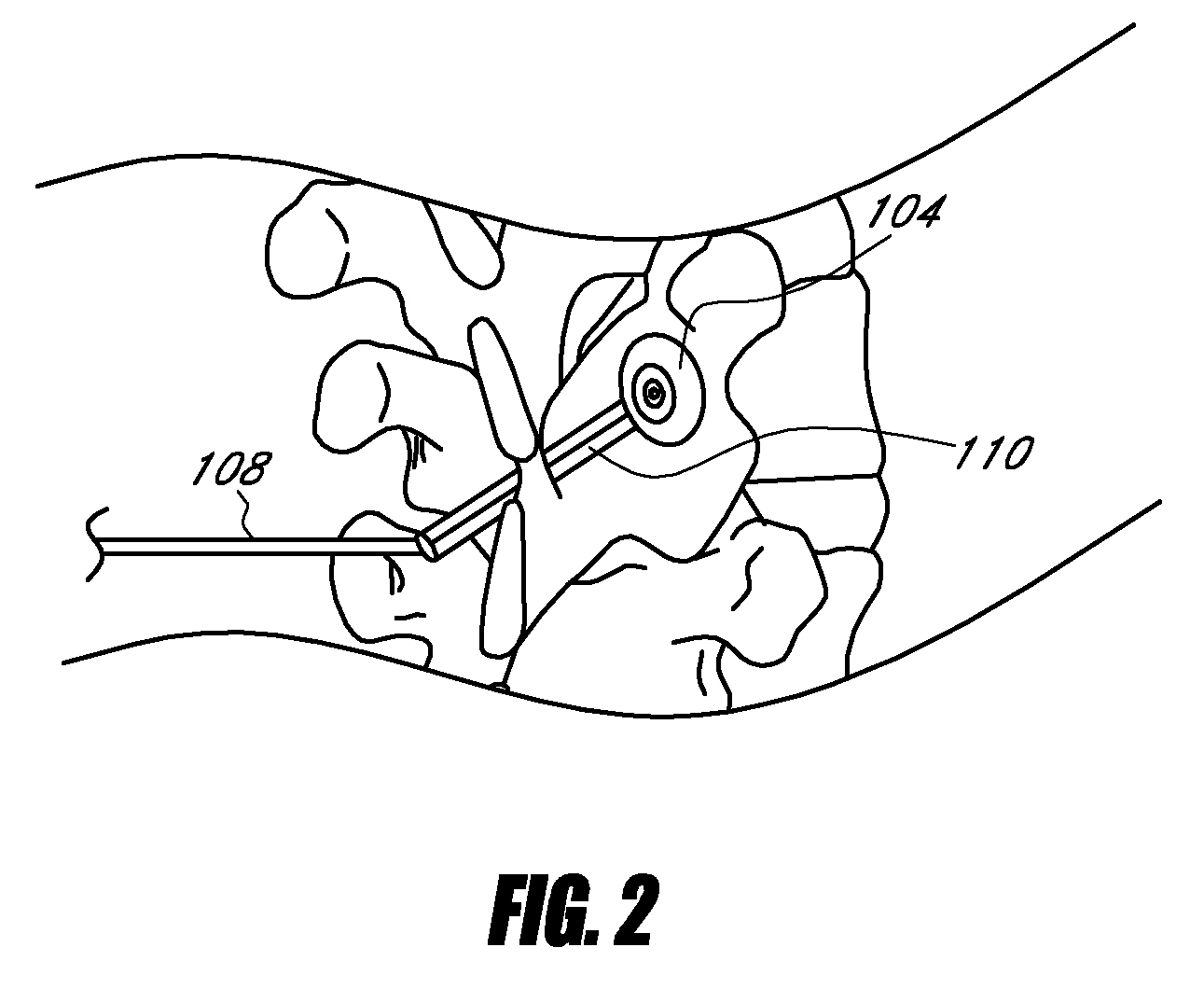
[0028]The following description and the accompanying figures, which describe and show certain preferred embodiments, are intended to demonstrate several possible configurations that systems for adjusting anatomical structures can take to include various aspects and features of the invention. The illustrated embodiments are shown correcting a scoliotic curvature of a spine. The illustration of embodiments in this context is not intended to limit the disclosed aspects and features of the invention to the specified embodiments or to usage only in correcting scoliosis. Those of skill in the art will recognize that the disclosed aspects and features of the invention are not limited to any specifically disclosed embodiment, and systems which include one or more of the inventive aspects and features herein described can be designed for use in a variety of applications.

[0029]As used herein, the term “vertical” refers to a direction generally in line with, or generally parallel to, a sagitta...


PUM


Abstract

A system for correcting a spinal deformity includes an implant fixed to one side of a vertebra and a rod extending along an axis of the spine on a second side of the vertebra. An adjustment member, which may include a reel, is coupled to the rod. A force directing member, such as a cable, extends between the rod and the adjustment member. The force directing member is retractable toward and extendible from the adjustment member. A method of correcting spinal deformity includes providing an implant, a rod, an adjustment member coupled to the rod, and a force directing member extending between the rod and the adjustment member. The adjustment member can be retractable toward and extendible from the adjustment member.

Description

CROSS-REFERENCE TO RELATED APPLICATIONS[0001]This application claims the benefit under 35 U.S.C. §119(e) of U.S. Provisional Application No. 60 / 933,326, filed Jun. 6, 2007. The disclosure of the above-referenced application is hereby expressly incorporated by reference in its entirety.BACKGROUND OF THE INVENTION[0002]1. Field of the Invention[0003]This application generally relates to devices and methods for adjusting anatomical structures. More particularly, this application related to devices and methods for correcting skeletal deformities, such as spinal deformities.[0004]2. Description of the Related Art[0005]Certain spine conditions, defects, deformities (e.g., scoliosis) as well as injuries may lead to structural instabilities, nerve or spinal cord damage, pain or other manifestations. Back pain (e.g., pain associated with the spinal column or mechanical back pain) may be caused by structural defects, by injuries or over the course of time from the aging process. For example, ...

Claims


Application Information

Patent Timeline
Patent Type & Authority Patents(United States)
IPC IPC(8): A61B17/70A61B17/04
CPCA61B17/7041A61B17/7053A61B17/707A61B2017/00017A61B2017/00212A61B2017/00221A61B2017/564
Inventor SACHS, DANSTONE, CORBETT
Owner K2M
Why Eureka
Try Eureka