Communication apparatus and communication method

Active Publication Date: 2012-05-15
FUJITSU LTD
View PDF8 Cites 2 Cited by
  • Summary
  • Abstract
  • Description
  • Claims
  • Application Information

AI Technical Summary

Benefits of technology

[0017]However, in any of the above prior art methods, a large amount of computation has to be performed to estimate the transmitted signals, because each method involves gradually reducing the number of transmitted signal candidate sets while calculating the metrics for a plurality of transmitted signal candidate sets. As a result, if these computations are to be performed without reducing the communication speed, the amount of computing circuitr

Problems solved by technology

However, in any of the above prior art methods, a large amount of computation has to be performed to estimate the transmitted signals, because each method involves gradually reducing the number of transmitted signal candidate sets while calculating the me

Method used


Image

  • Communication apparatus and communication method
  • Communication apparatus and communication method
  • Communication apparatus and communication method

Examples


first embodiment

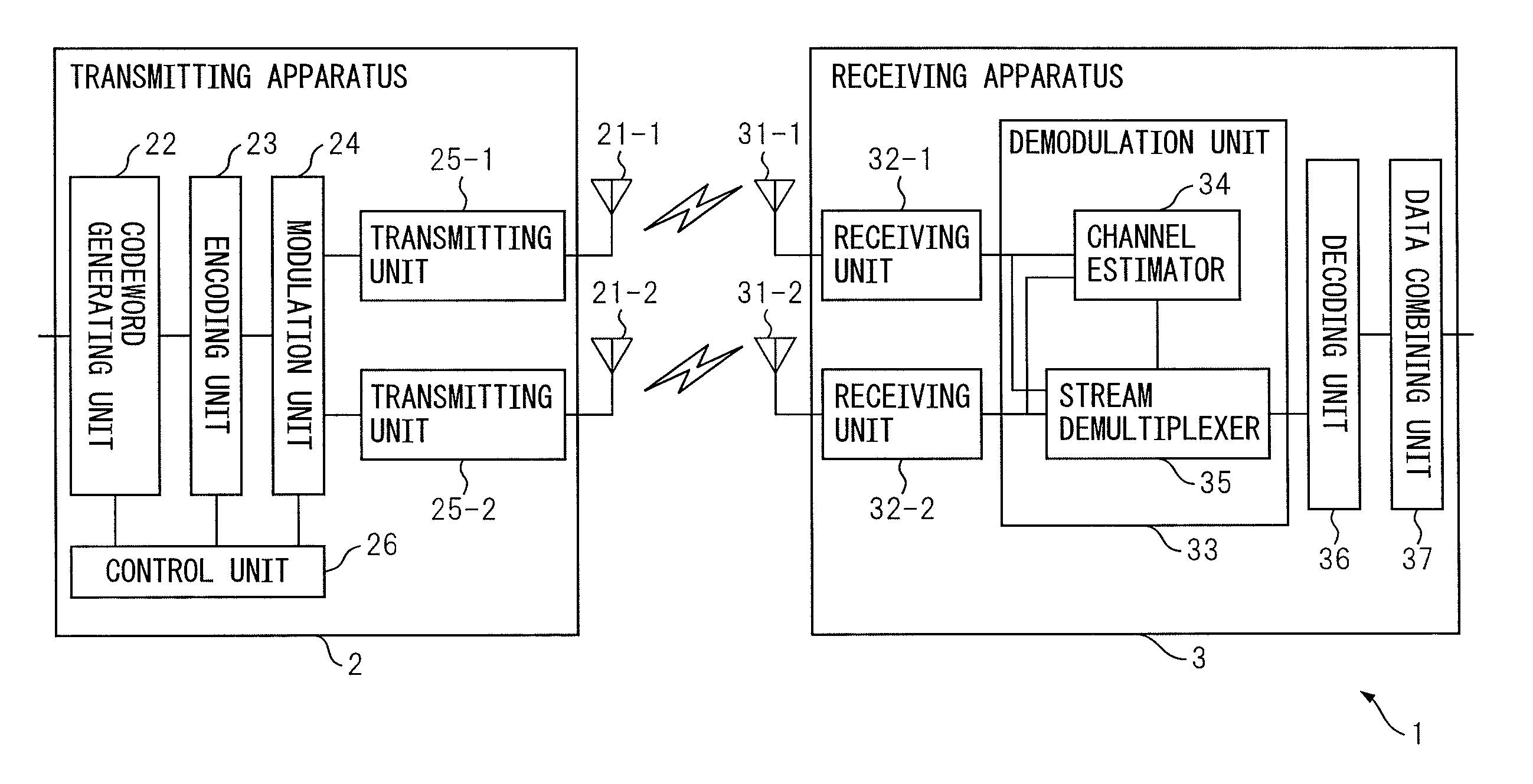
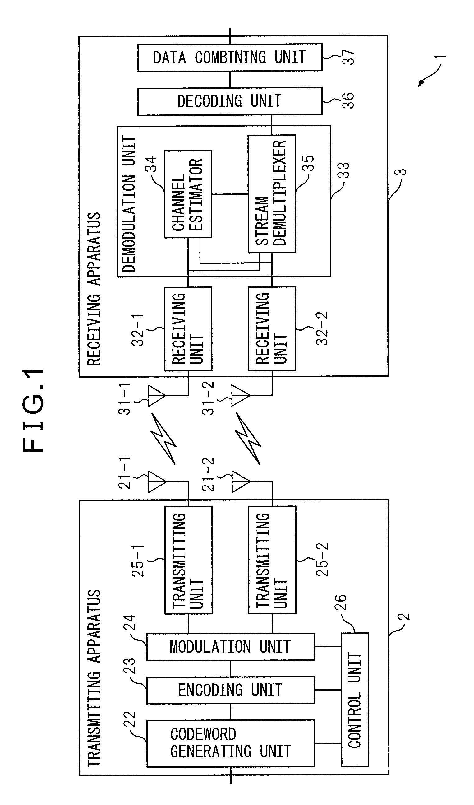
[0038]FIG. 1 is a diagram schematically illustrating the configuration of a communication system 1 which includes a receiving apparatus 3 according to a The communication system 1 includes a transmitting apparatus 2 equipped with two antennas 21-1 and 21-2, as well as the receiving apparatus 3 which is also equipped with two antennas 31-1 and 31-2. The transmitting apparatus 2 radiates transmitted signals as radio signals simultaneously from the respective antennas 21-1 and 21-2. On the other hand, the receiving apparatus 3 receives the transmitted signals from the transmitting apparatus 2 by the respective antennas 31-1 and 31-2. The signals received by the respective antennas 31-1 and 31-2 will hereinafter be referred to as the received signals. The receiving apparatus 3 recovers the transmitted signals based on each received signal.

[0039]In the present embodiment, the number of antennas mounted on the transmitting apparatus 2 is only illustrative, and may be set to any number no...

second embodiment

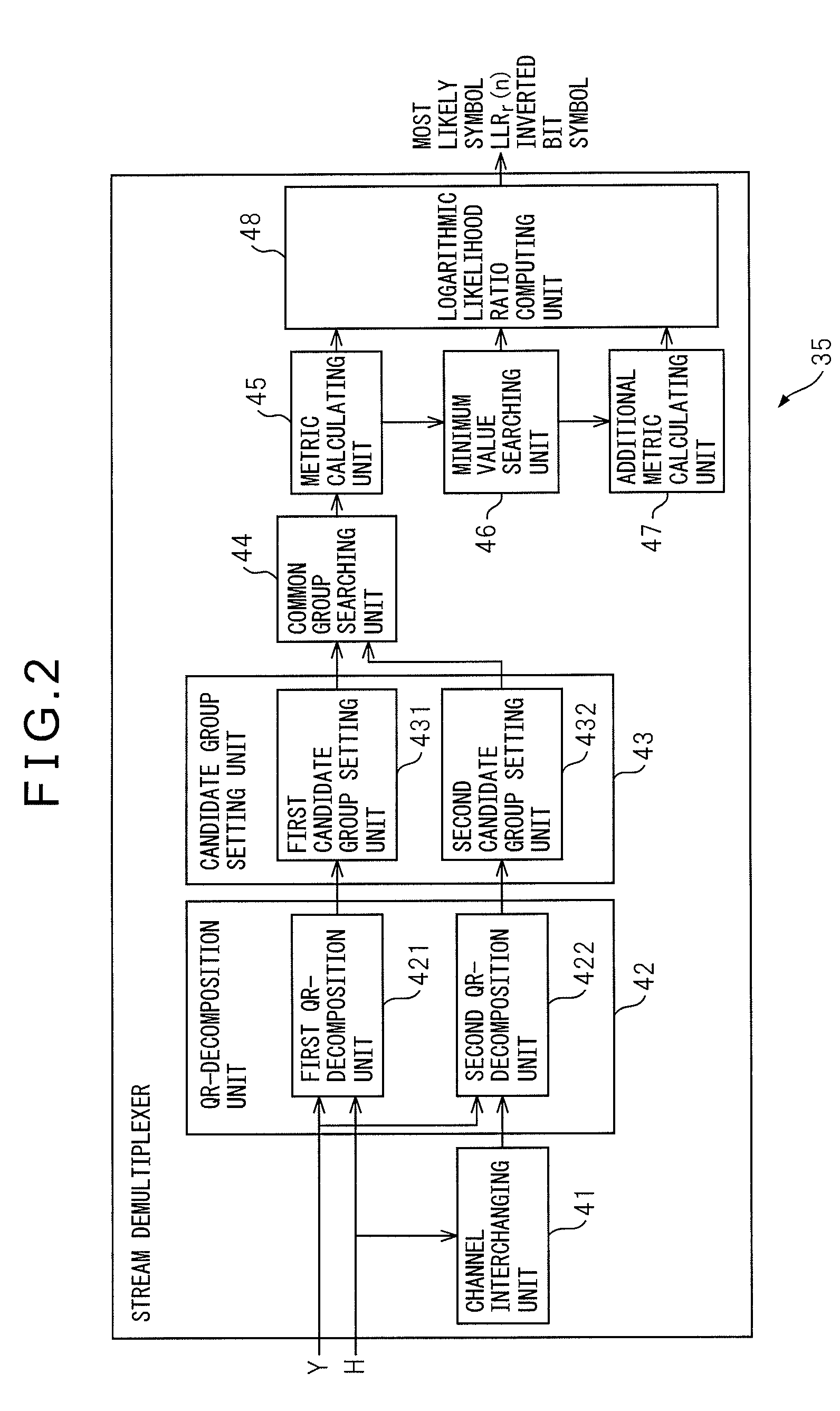
[0127]FIG. 9 is a diagram schematically illustrating the configuration of the stream demultiplexer 351 in the receiving apparatus according to the The stream demultiplexer 351 includes a channel interchanging unit 41, a QR-decomposition unit 42, a candidate group setting unit 43, a common group searching unit 44, a metric calculating unit 45, a minimum value searching unit 46, an additional metric calculating unit 47, a logarithmic likelihood ratio computing unit 48, and a ranking unit 51.

[0128]These units constituting the stream demultiplexer 351 may be implemented as separate computing circuits. Alternatively, these units constituting the stream demultiplexer 351 may be integrated into a single computing circuit implementing the functions of the respective units.

[0129]In FIG. 9, the units constituting the stream demultiplexer 351 are designated by the same reference numerals as those used to designate the corresponding component elements of the stream demultiplexer 35 according t...

third embodiment

[0165]FIG. 12 is a diagram schematically illustrating the configuration of the stream demultiplexer 352 in the receiving apparatus according to the The stream demultiplexer 352 includes a channel interchanging unit 41, a QR-decomposition unit 42, a candidate group setting unit 43, a common group searching unit 44, a metric calculating unit 45, a minimum value searching unit 46, an additional metric calculating unit 47, and a logarithmic likelihood ratio computing unit 48.

[0166]These units constituting the stream demultiplexer 352 may be implemented as separate computing circuits. Alternatively, these units constituting the stream demultiplexer 352 may be integrated into a single computing circuit implementing the functions of the respective units.

[0167]In FIG. 12, the units constituting the stream demultiplexer 352 are designated by the same reference numerals as those used to designate the corresponding component elements of the stream demultiplexer 35 according to the first embod...


PUM


Abstract

A communication apparatus calculates a residual component by noting one of a given plurality of transmitted signals and by canceling a component corresponding to a candidate/candidates for the other/others of the plurality of transmitted signals from a signal corresponding to one of a plurality of received signals. The communication apparatus determines a candidate for the given transmitted signal by selecting a value closest to the residual component from among the values that the given transmitted signal can take, and obtains a plurality of candidate groups by changing that given transmitted signal, each candidate group being constructed as a collection of candidate sets each comprising a candidate for that given transmitted signal and a candidate/candidates for that other transmitted signal/signals. Then, the communication apparatus selects transmitted signal candidate sets that are common to the plurality of candidate groups and estimates the plurality of transmitted signals using the selected candidate sets.

Description

CROSS-REFERENCE TO RELATED APPLICATION[0001]This application is based upon and claims the benefit of priority of the prior Japanese Patent Application No. 2010-106243, filed on May 6, 2010, the entire contents of which are incorporated herein by reference.FIELD[0002]The embodiments discussed herein are related to a communication apparatus and communication method wherein signals transmitted from a plurality of different antennas are received using a plurality of antennas.BACKGROUND[0003]There has long been a need to enhance data transmission speed in wireless communications. To address this, work on next-generation data communication standards, such as Long Term Evolution (LTE) has been proceeding. In high-speed data communication standards such as LTE, Multiple Input Multiple Output (MIMO) technology has been attracting attention, since it can apparently increase the bandwidth by transmitting and receiving signals in parallel using multiple antennas at both the transmitting and rec...

Claims


Application Information

Patent Timeline
IPC IPC(8): H04B7/02H04L1/02
CPCH04J11/004H04L25/0206H04L25/03891H04L25/03203H04L25/03292H04L25/03318H04L25/03197H04L1/0045H04L25/0246H04L25/0204
Inventor SEYAMA, TAKASHI
Owner FUJITSU LTD
Why Eureka
Try Eureka