AI technical title is built by Patsnap AI team. It summarizes the technical point description of the patent document.
a technology for armrests and chairs, applied in the field of chairs, can solve the problems of inability to provide a sufficiently stable position, the armrest may move to an undesired position, and the locking mechanism often requires a relatively high amount of for
Active Publication Date: 2012-08-21
KNOLL INC
View PDF25 Cites 33 Cited by
Summary
Abstract
Description
Claims
Application Information
AI Technical Summary
This helps you quickly interpret patents by identifying the three key elements:
Problems solved by technology
Method used
Benefits of technology
Benefits of technology
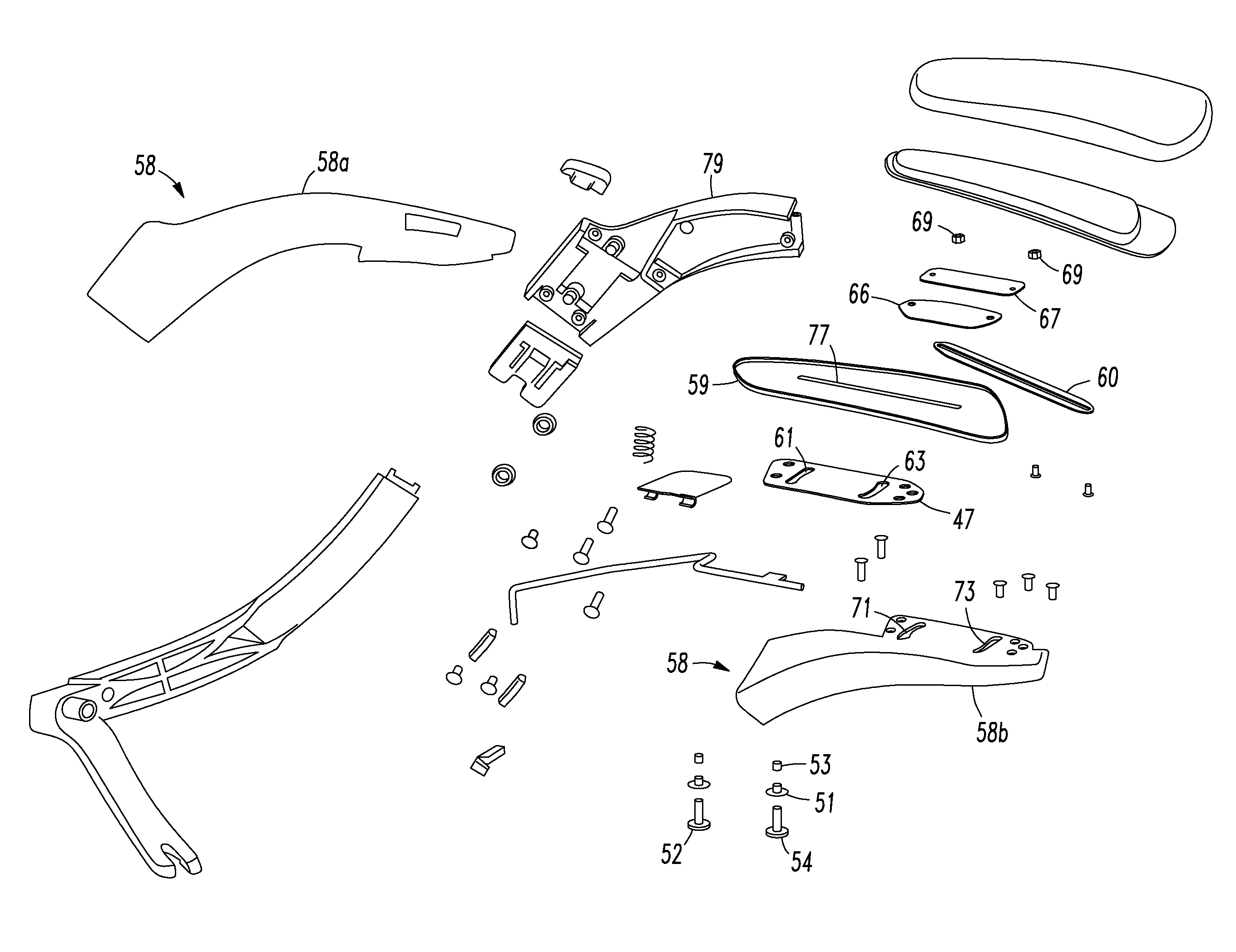
[0011]Embodiments of our chair may include a resilient device that is comprised of a leaf spring positioned above a tapped plate. The leaf spring has a first hole and a second hole. The first hole of the leaf spring may be the first hole of the resilient device and the second hole of the leaf spring may be the second hole of the resilient device. The tapped plate may include a first hole aligned with the first hole of the leaf spring and a second hole aligned with the second hole of the leaf spring. The first member extends through the first hole of the leaf spring and the first hole of the tapped plate. The second member extends through the second hole of the leaf spring and the second hole of the tapped plate. The first and second members may be adjustably attached to the tapped plate and leaf spring such that adjustment of the first and second members can loosen or tighten the positioning of the leaf spring relative to the tapped plate.
Problems solved by technology
One problem many users experience with adjustable armrest designs is their inability to provide a sufficiently stable position.
However, when a user may lean on the armrest, that armrest may move to an undesired position due to the force exerted on the armrest by the user.
For instance, such locking mechanisms often require a relatively high amount of force to press a button or actuate a lever to unlock the locking device prior to adjusting the position of the armrest.
Method used
Image
Click on the blue label to locate the original text in one second.
Reading with bidirectional positioning of images and text.
Examples
Embodiment Construction
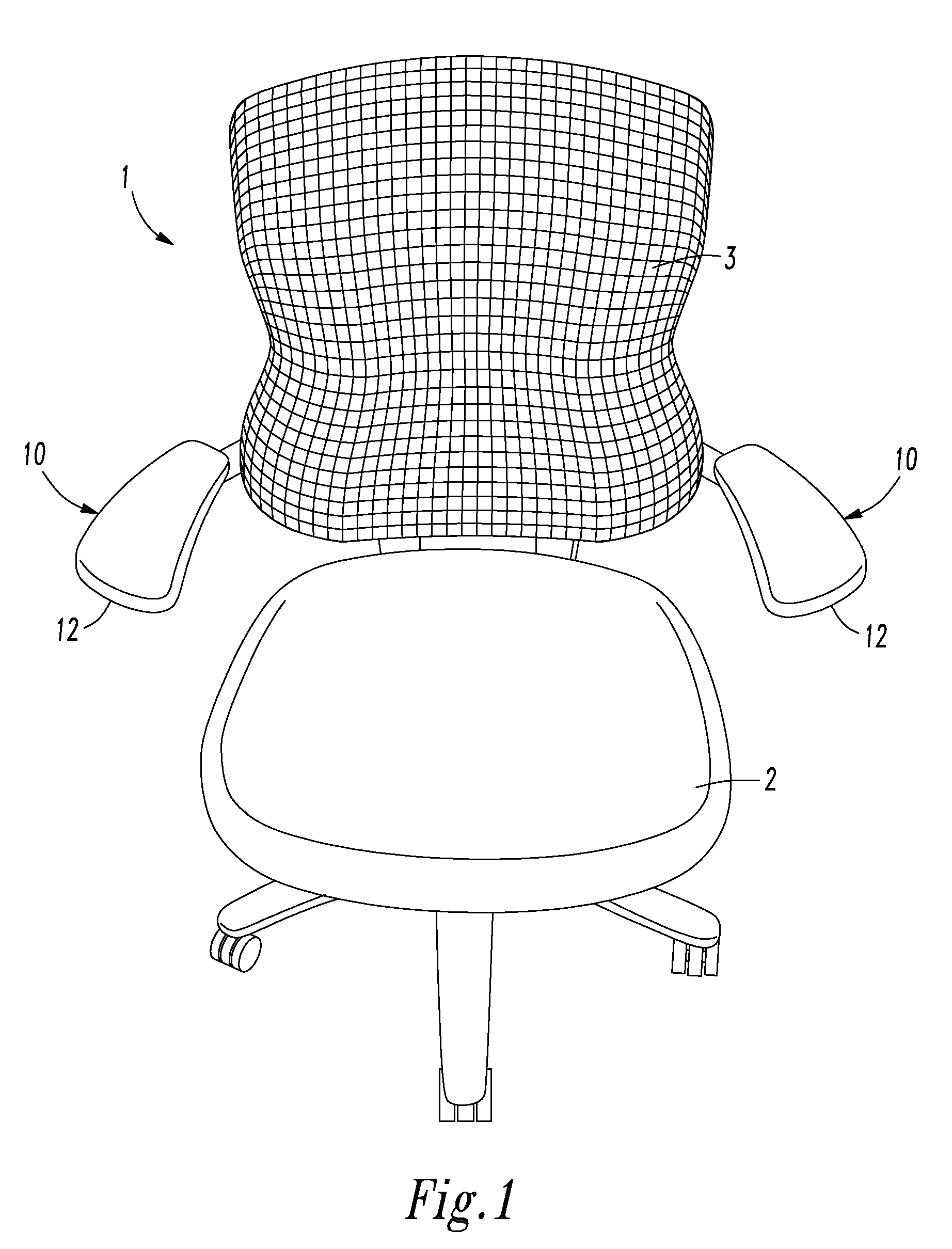
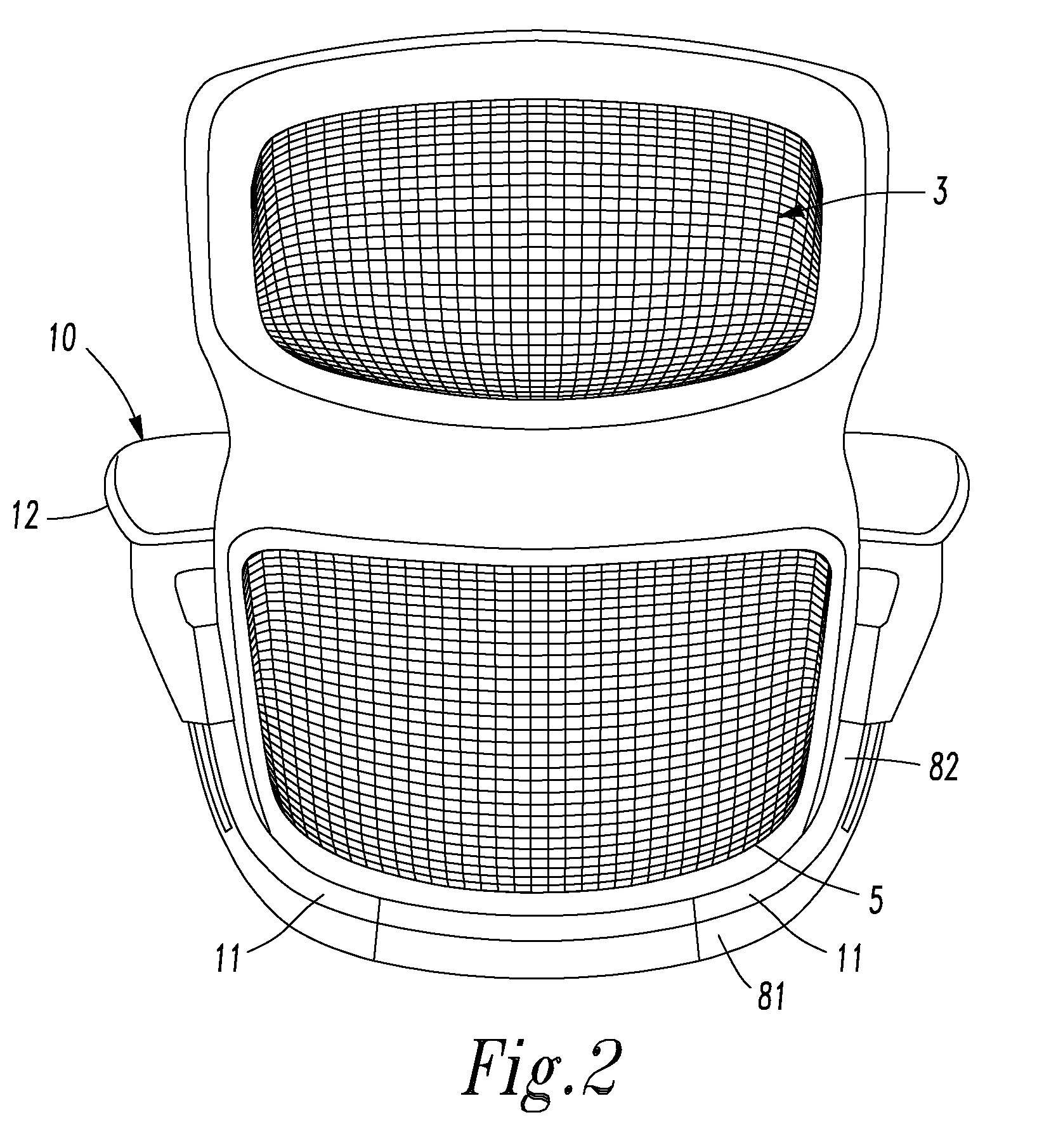
[0054]Referring to FIGS. 1-2, a chair 1 has a seat 2 and a back 3. The back 3 includes a back frame 5 and a skin attached to the back frame. The back skin is configured to be engaged by a user sitting in the chair. An armrest apparatus 10 is positioned adjacent each side of the back 3. Each armrest apparatus 10 includes an armrest support 11 that is attached to the bottom of the back frame 5 and an arm pad 12. The arm pad 12 is connected to the armrest support 11 such that the arm pad 12 may be located at numerous different vertical positions adjacent the seat 2 and the back 3. Each arm pad 12 may be composed of a rigid plastic that provides a surface for supporting an arm or other body part of a user. Of course, the arm pad 12 may alternatively be composed of a fabric covering a cushion, other types of plastic such as soft or flexible plastic, or have other constructions known to those skilled in the art.
[0055]As may be seen in FIGS. 3 through 7, the arm pad 12 is attached to an ar...
PUM
Abstract
An armrest apparatus and chair including one or more armrest apparatuses are disclosed. Each armrest apparatus includes an armrest member attached to at least one chair component. The armrest member has a first aperture and a second aperture. A first plate is positioned above the armrest member. The first plate has a longitudinal slot that is transverse to the first and second apertures. An armrest cover is attached to the first plate. A resilient device is positioned between the first plate and the armrest cover or between the first plate and the armrest member. The resilient device has a first hole sized and configured to receive the first member and a second hole sized and configured to receive the second member. A first member extends through the first aperture, first hole and the longitudinal slot and a second member extends through the second aperture, second hole and the longitudinal slot.
Description
CROSS-REFERENCE TO RELATED APPLICATION[0001]The present application claims the benefit under 35 U.S.C. §119(e) of pending U.S. Provisional Patent Application Ser. No. 61 / 059,297, which was filed on Jun. 6, 2008. The entirety of U.S. Provisional Patent Application Ser. No. 61 / 059,297 is incorporated herein by reference.FIELD OF THE INVENTION[0002]The present invention relates to chairs, particularly armrest devices for chairs.BACKGROUND OF THE INVENTION[0003]Adjustable armrests are disclosed in U.S. Pat. Nos. 7,234,779, 6,840,582, 6,802,566, 6,659,561, 6,540,300, 5,975,640, 5,971,484, 5,876,097, 5,676,483, 5,599,067, 5,597,208, 5,484,187, 5,439,267, 5,415,459, 5,393,124, 5,265,938, 5,188,423, 5,056,863, and 4,961,610, U.S. Provisional Patent Application No. 60 / 953,213 and World Intellectual Property Organization Publication No. WO2008 / 112920. Such armrests typically permit a user to adjust an armrest laterally, rotationally, or longitudinally so the user may adjust the support provid...
Claims
Application Information
Patent Timeline
Application Date:The date an application was filed.
Publication Date:The date a patent or application was officially published.
First Publication Date:The earliest publication date of a patent with the same application number.
Issue Date:Publication date of the patent grant document.
PCT Entry Date:The Entry date of PCT National Phase.
Estimated Expiry Date:The statutory expiry date of a patent right according to the Patent Law, and it is the longest term of protection that the patent right can achieve without the termination of the patent right due to other reasons(Term extension factor has been taken into account ).
Invalid Date:Actual expiry date is based on effective date or publication date of legal transaction data of invalid patent.

