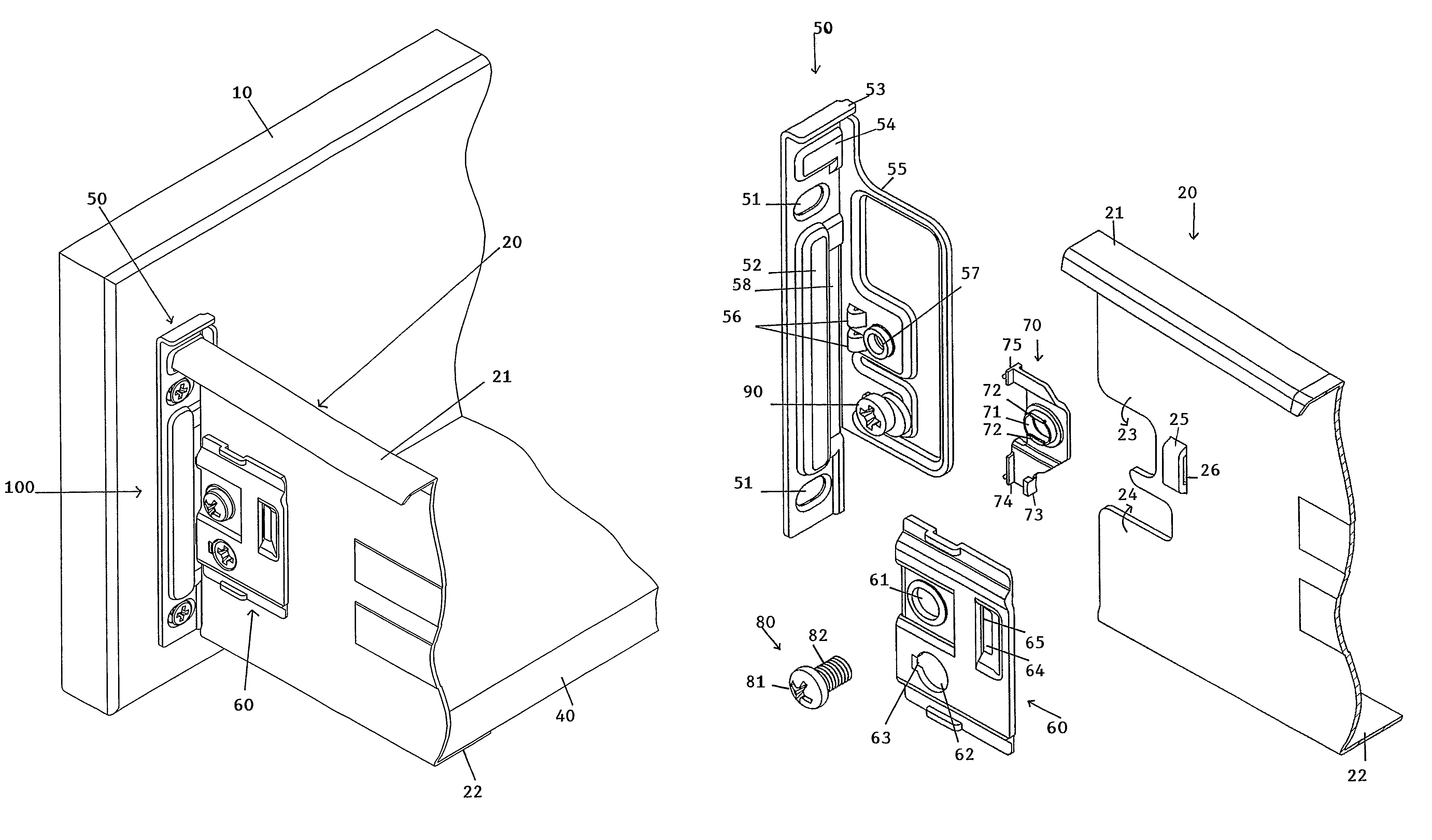
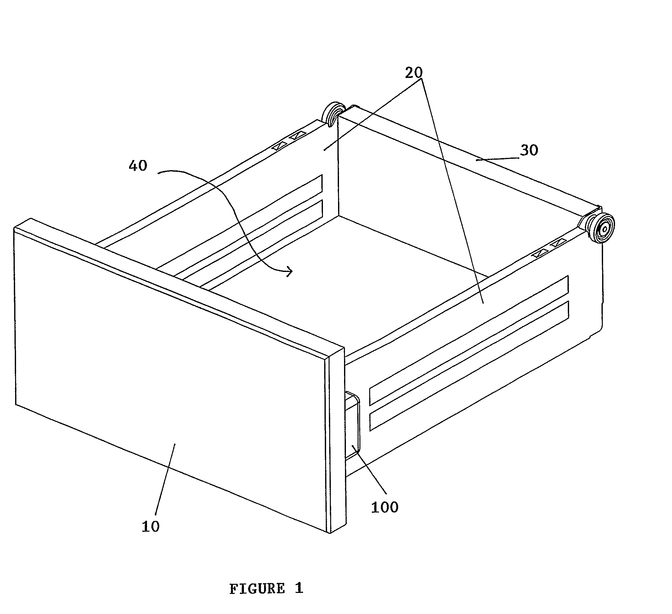
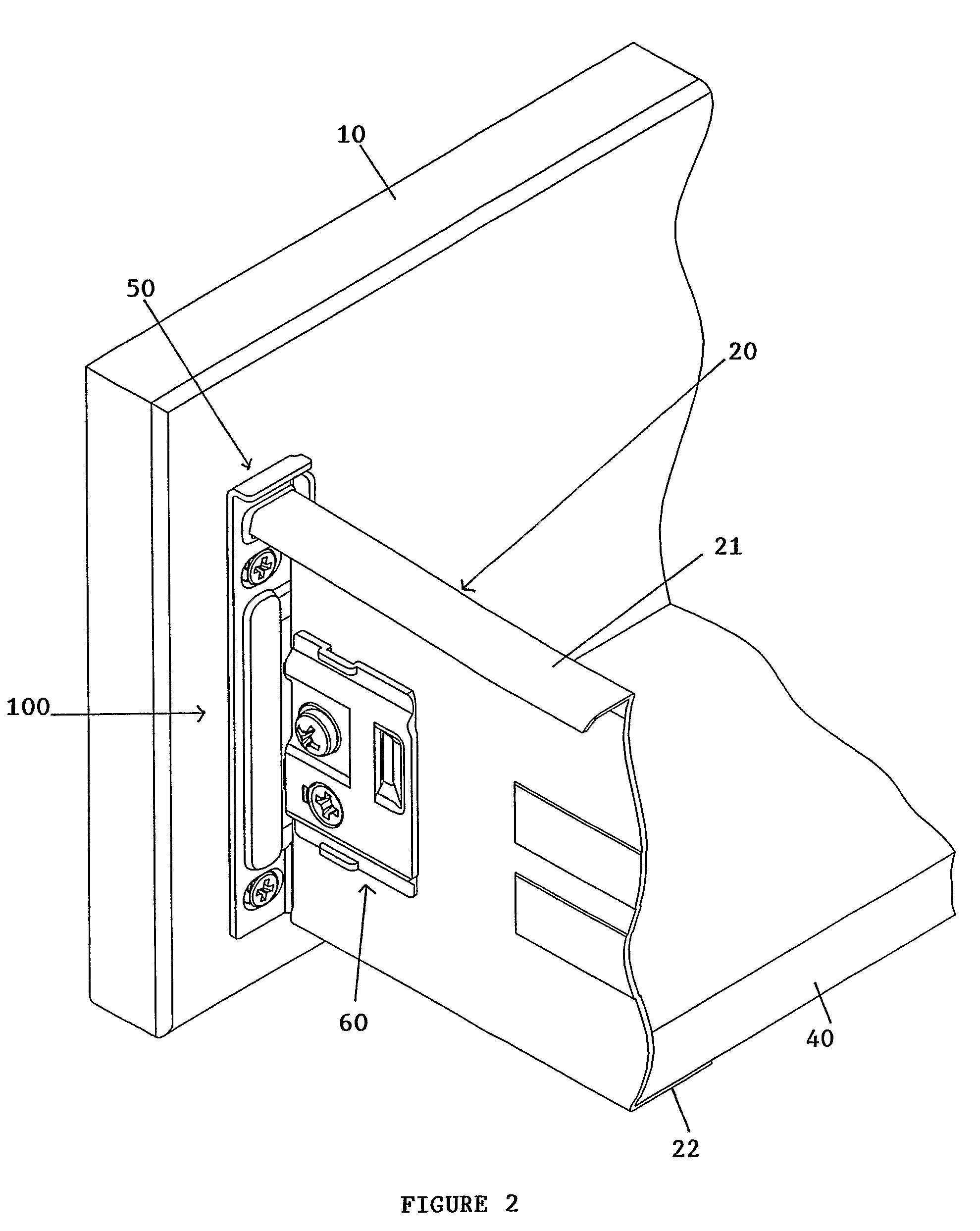
[0011]In accordance with an aspect of the invention, there is provided a drawer fitting for fixing a drawer side to a drawer front panel, the fitting comprising a holding plate for mounting the fitting to the drawer front panel, the holding plate having a flange extending in a direction parallel to a drawer side, the flange having a forwardly-disposed guide formation, a clamping plate having a forwardly-disposed angled flange, a guide clip mountable on the clamping plate such that the drawer side front end can be positioned between the holding plate flange and the guide clip, the guide clip having resiliently depressible projecting tails, and an assembly screw that passes through and couples together the clamping plate and guide clip, and the screw being received in an aperture in said holding plate flange through a recess in the front end of the drawer side. When clamping force is applied to the fitting by tightening the assembly screw, the clamping plate angled flange rides over the holding plate guide formation so as to simultaneously move the clamping plate with clip both forwardly towards the front panel and laterally towards the holding plate flange, movement of the clamping plate toward the drawer front panel causing the guide clip projecting tails to be pressed in at the rear of the drawer front panel. When the assembly is loosened by unscrewing the assembly screw, the projecting tails relax to push the clamping plate with clip rearwardly while being withdrawn laterally under the screw action, thus maintaining the clamping plate and clip substantially parallel to the holding plate flange to facilitate adjustment or removal of the drawer side.
[0022]The aim of the invention is to provide a drawer fitting which permits secure anchoring of drawer sides to the drawer front panel, easy removal as well as adjustments during assembly of the drawer.
[0023]The action of the clamping plate angled plate riding over the holding plate flange guide formation when the assembly screw is tightened, ensures that the clamping plate is guided to be substantially parallel with both the side panel and front panel as it moves laterally towards the holding plate flange (side panel) and forwardly towards the holding plate (drawer front panel). Consequently, the flat face of the side panel projection abuts fully against the flat front edge of the clamping plate depression, thus ensuring proper engagement between the drawer side and clamping plate of drawer fitting (front panel).
[0024]Additionally, as mentioned above, the resilient guide clip projecting tails are pressed in at the rear of the drawer front panel when the assembly screw is tightened. Upon loosening of the assembly screw, the projecting tails are relaxed (reverting to original state) and urge the clamping plate angled flange back over the holding plate flange guide formation. The relaxing motion of the projecting tails at the rear of the front panel when clamping force is relieved, guides the clamping plate such that it remains substantially parallel to both the side panel and front panel whilst moving laterally and rearwardly away from both the holding plate and holding plate flange, respectively. This feature ensures that all the essential elements of the fitting and side panel, such as the flat face of the side panel projection and flat front edge of the clamping plate depression; and openings on the clamping plate, apertures on the holding plate flange and side panel recesses, remain in alignment during loosening and tightening of the assembly screw, allowing for the side panel to be easily adjustable or removable from the fitting (front panel).
[0025]Also, interaction between the retaining shoulders of the guide clip opening and the assembly screw (between screw head portion and thread portion) will ensure that the clamping plate is lifted from its engagement with the holding plate flange, in line with the movement of the assembly screw, when the assembly screw is loosened or unscrewed.
[0026]Furthermore, the locking stop formed between the side panel and clamping plate of the fitting is secure as the stop is formed from the interaction between the side panel projection flat face and the flat front edge of the clamping plate depression i.e. interaction between two substantially flat surfaces that overlie one another in a mutually parallel manner in the locked state. Such an interaction is very secure as the interacting surface area between the two elements is maximized in comparison to interaction between a flat surface and an angled or sloping surface. This allows the drawer fitting to be robust and able to withstand the drawer assembly being closed with excessive force without the drawer side being disengaged from the front panel.

