Drawer fitting

a technology for drawers and fittings, applied in drawers, furniture parts, domestic applications, etc., can solve the problems of side panels being disengaged from front panel fittings, sideways tilting or twisting of clamping/pressing plates, and the side panels being less than secure between the drawer fittings and the side panels. to achieve the effect of robustness of the drawer fitting

Inactive Publication Date: 2009-07-09
HARN MARKETING
View PDF8 Cites 47 Cited by
  • Summary
  • Abstract
  • Description
  • Claims
  • Application Information

AI Technical Summary

Benefits of technology

[0011]In accordance with an aspect of the invention, there is provided a drawer fitting for fixing a drawer side to a drawer front panel, the fitting comprising a holding plate for mounting the fitting to the drawer front panel, the holding plate having a flange extending in a direction parallel to a drawer side, the flange having a forwardly-disposed guide formation, a clamping plate having a forwardly-disposed angled flange, a guide clip mountable on the clamping plate such that the drawer side front end can be positioned between the holding plate flange and the guide clip, the guide clip having resiliently depressible projecting tails, and an assembly screw that passes through and couples together the clamping plate and guide clip, and the screw being received in an aperture in said holding plate flange through a recess in the front end of the drawer side. When clamping force is applied to the fitting by tightening the assembly screw, the clamping plate angled flange rides over the holding plate guide formation so as to simultaneously move the clamping plate with clip both forwardly towards the front panel and laterally towards the holding plate flange, movement of the clamping plate toward the drawer front panel causing the guide clip projecting tails to be pressed in at the rear of the drawer front panel. When the assembly is loosened by unscrewing the assembly screw, the projecting tails relax to push the clamping plate with clip rearwardly while being withdrawn laterally under the screw action, thus maintaining the clamping plate and clip substantially parallel to the holding plate flange to facilitate adjustment or removal of the drawer side.
[0022]The aim of the invention is to provide a drawer fitting which permits secure anchoring of drawer sides to the drawer front panel, easy removal as well as adjustments during assembly of the drawer.
[0023]The action of the clamping plate angled plate riding over the holding plate flange guide formation when the assembly screw is tightened, ensures that the clamping plate is guided to be substantially parallel with both the side panel and front panel as it moves laterally towards the holding plate flange (side panel) and forwardly towards the holding plate (drawer front panel). Consequently, the flat face of the side panel projection abuts fully against the flat front edge of the clamping plate depression, thus ensuring proper engagement between the drawer side and clamping plate of drawer fitting (front panel).
[0024]Additionally, as mentioned above, the resilient guide clip projecting tails are pressed in at the rear of the drawer front panel when the assembly screw is tightened. Upon loosening of the assembly screw, the projecting tails are relaxed (reverting to original state) and urge the clamping plate angled flange back over the holding plate flange guide formation. The relaxing motion of the projecting tails at the rear of the front panel when clamping force is relieved, guides the clamping plate such that it remains substantially parallel to both the side panel and front panel whilst moving laterally and rearwardly away from both the holding plate and holding plate flange, respectively. This feature ensures that all the essential elements of the fitting and side panel, such as the flat face of the side panel projection and flat front edge of the clamping plate depression; and openings on the clamping plate, apertures on the holding plate flange and side panel recesses, remain in alignment during loosening and tightening of the assembly screw, allowing for the side panel to be easily adjustable or removable from the fitting (front panel).
[0025]Also, interaction between the retaining shoulders of the guide clip opening and the assembly screw (between screw head portion and thread portion) will ensure that the clamping plate is lifted from its engagement with the holding plate flange, in line with the movement of the assembly screw, when the assembly screw is loosened or unscrewed.
[0026]Furthermore, the locking stop formed between the side panel and clamping plate of the fitting is secure as the stop is formed from the interaction between the side panel projection flat face and the flat front edge of the clamping plate depression i.e. interaction between two substantially flat surfaces that overlie one another in a mutually parallel manner in the locked state. Such an interaction is very secure as the interacting surface area between the two elements is maximized in comparison to interaction between a flat surface and an angled or sloping surface. This allows the drawer fitting to be robust and able to withstand the drawer assembly being closed with excessive force without the drawer side being disengaged from the front panel.

Problems solved by technology

Such interaction between a flat face and an angled face will result in a less than secure engagement between the side panel and the drawer fitting.
As a result, both these wedge noses / portions may be disengaged from their respective side panel slots, resulting in disengagement of the side panels from the fittings mounted on the front panel.
However, it is imperative that these movements are guided to be substantially parallel with both the side panel and the front panel as the lack of a suitable guide means, will likely result in sideways tilting or twisting of the clamping / pressing plate, during tightening of the attachment screw.
This will inevitably result in misalignment of the wedge nose / portions with its corresponding side panel slot, and therefore, improper engagement between the side panel and fitting (front panel).
Therefore, in both cases, secure engagement of the side panel to the drawer front panel as well as parallel alignment of the two side panels on either sides of the drawer assembly will be made unduly difficult and depend largely on the skill of the user assembling these fittings.

Method used


Image

  • Drawer fitting
  • Drawer fitting
  • Drawer fitting

Examples


Embodiment Construction

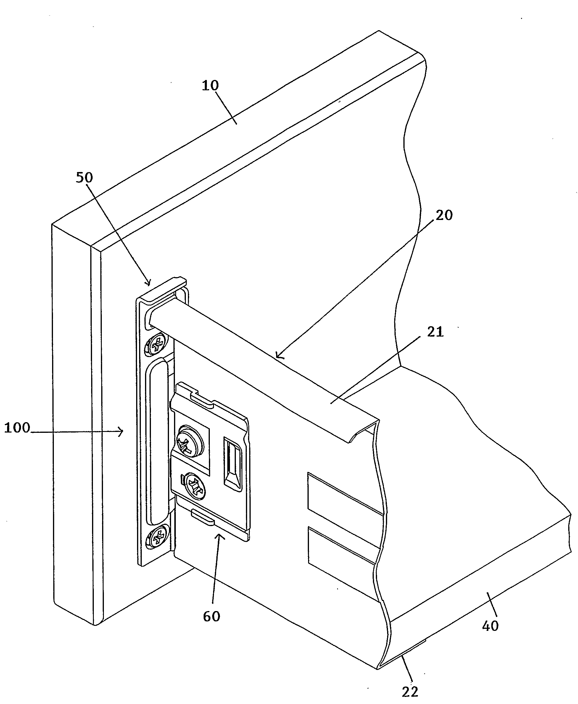
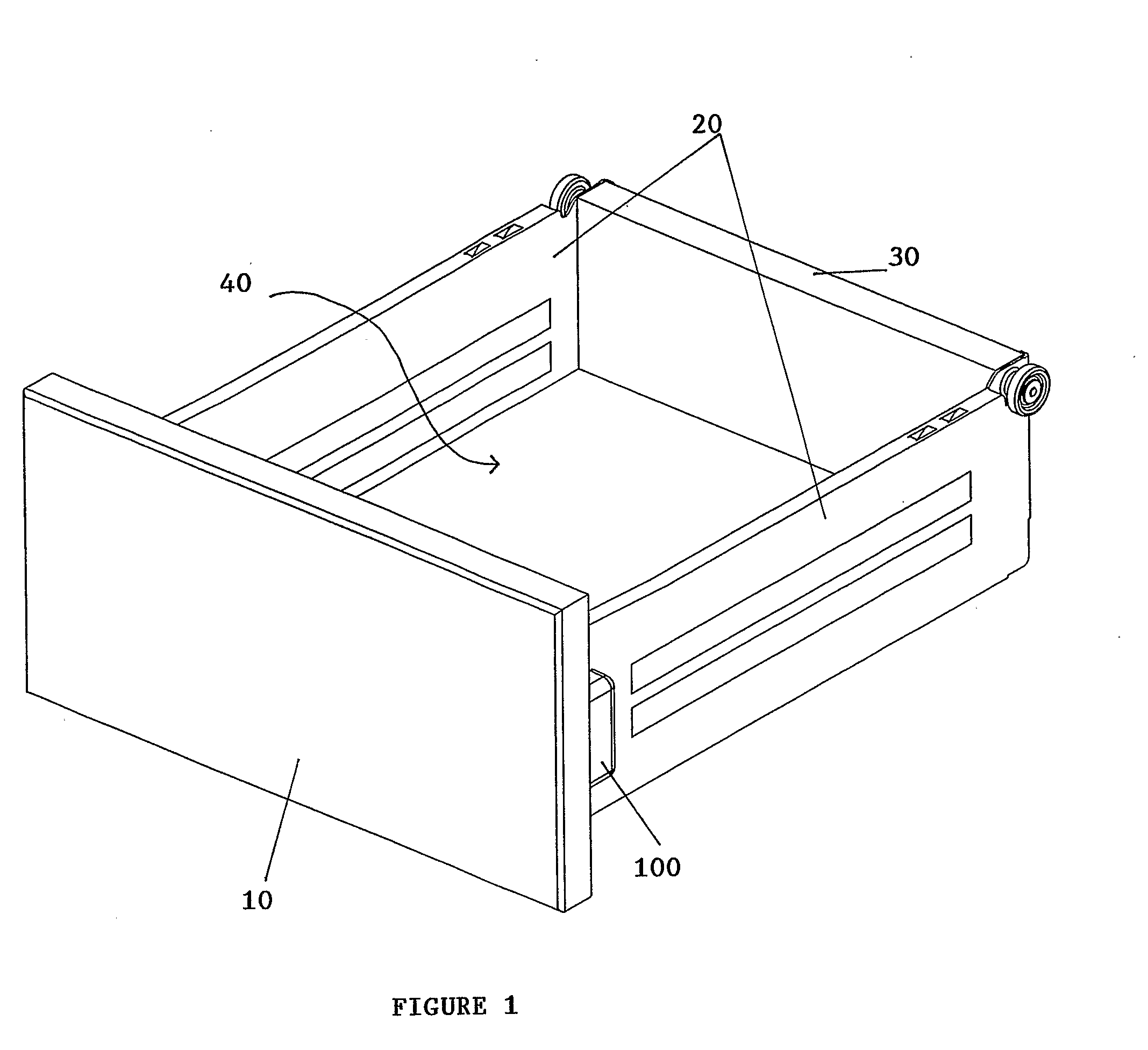
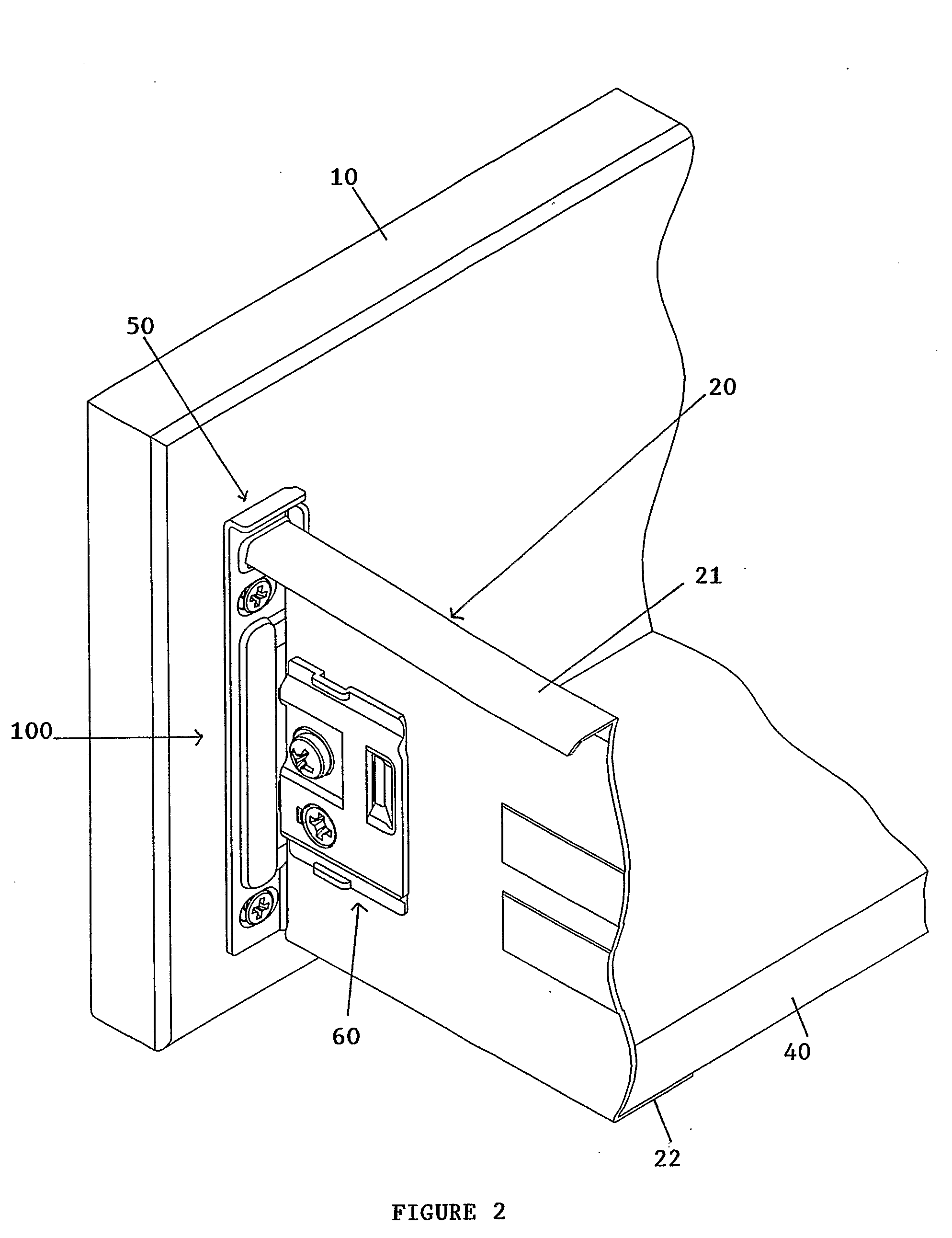
[0037]FIGS. 1 and 2 show a drawer assembly comprising a front panel 10, a rear panel 30, a bottom panel 40 as well as drawer sides 20 extending between the front 10 and rear 30 panels at each side of the drawer assembly. The bottom 40 and rear 30 panels of the drawer are joined to the drawer sides 20 in a conventional manner. The drawer sides 20 are preferably made of metal material with each drawer side 20 fixed to a longitudinal end of the drawer front panel 10 by a drawer fitting 100 of the present invention. A preferred embodiment of the drawer fitting 100 of this invention is seen in FIG. 3. This drawer fitting 100 comprises a holding plate 50, a clamping plate 60, a guide clip 70 as well as an assembly screw 80.

[0038]The holding plate 50 of the drawer fitting 100 is preferably made of metal and mounted at a longitudinal end of the rear surface of the drawer front panel 10 via screws (or the like) through openings 51 provided towards the top and bottom portion of the holding pl...


PUM


Abstract

A drawer fitting for fixing a drawer side to a drawer front panel is disclosed. The fitting includes a holding plate for mounting the fitting to the drawer front panel, the holding plate having a flange extending in a direction parallel to a drawer side, the flange having forwardly-disposed guide noses, a clamping plate having a forwardly-disposed angled flange, a guide clip mountable on the clamping plate such that the drawer side front end can be positioned between the holding plate flange and the guide clip, the guide clip having resiliently depressible projecting tails and an assembly screw that passes through and couples together the clamping plate and guide clip, and is received in an aperture in said holding plate flange through a recess in the front end of the drawer side.

Description

[0001]The invention relates to a drawer fitting for use in a knock-down drawer assembly and more particularly a fitting for fixing the drawer sides to the front panel of the drawer assembly.DESCRIPTION OF THE PRIOR ART[0002]Drawer assemblies are often designed to be knocked down for the purposes of ease of transportation or flexibility of configuration. The knocked down parts of drawers of this type must be easily assembled by the general public without the requirement of specialized tools or skills. Known knock-down drawer assemblies generally consist of a bottom panel, a front panel, a back panel and a pair of side panels affixed to and extending parallel between the front and rear panels as well as engaged with the bottom panel along its longitudinal length.[0003]With new construction materials and methods, drawers are no longer solely made from wood or wood products; other materials such as formed sheet metals or plastic moldings are increasingly being used. It is now common to ...

Claims


Application Information

Patent Timeline
Patent Type & Authority Applications(United States)
IPC IPC(8): A47B88/00
CPCA47B88/0055A47B2088/0066A47B2088/0062A47B88/956A47B2088/952A47B2088/953
Inventor LAM, HARN LIANLAM, HARN YAN
Owner HARN MARKETING
Why Eureka
Try Eureka