Impact resistant implantable antenna coil assembly
- Summary
- Abstract
- Description
- Claims
- Application Information
AI Technical Summary
Benefits of technology
Problems solved by technology
Method used
Image

Examples
first embodiment
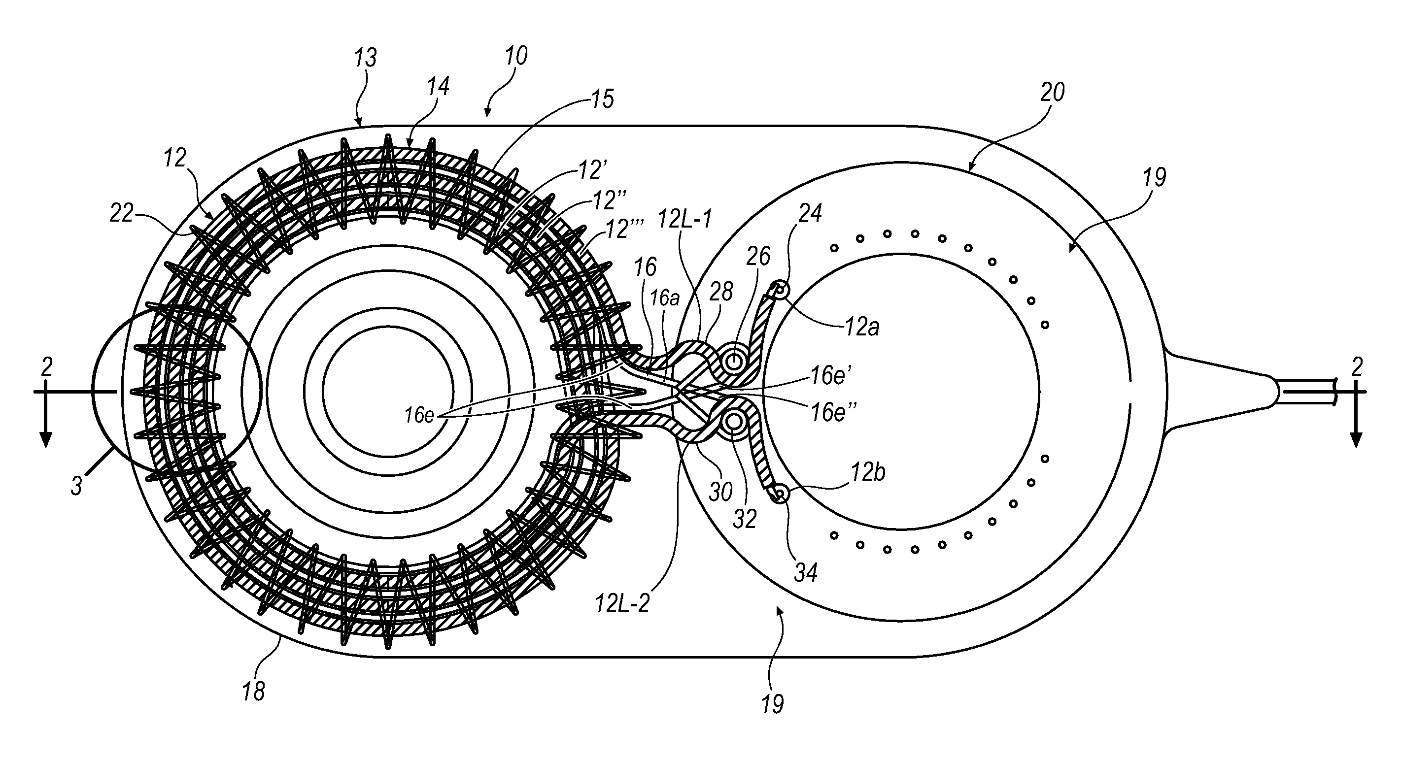
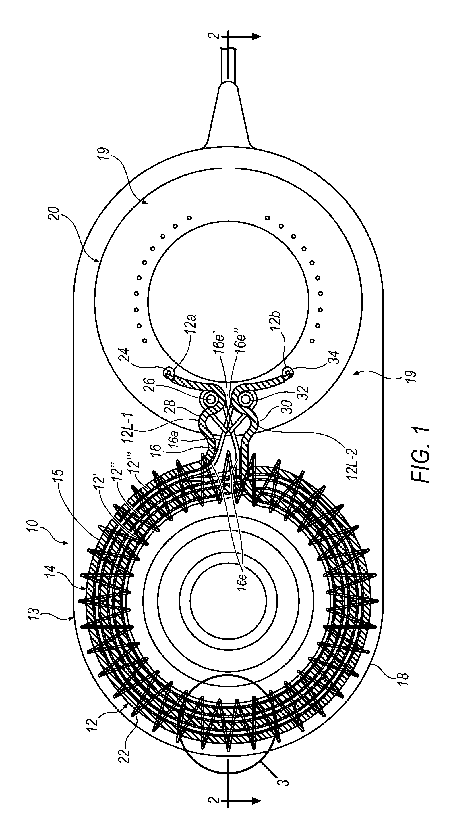
[0033]The second of the several embodiments of the present invention possessing the foregoing non-orthogonal impact force resistant features is illustrated in FIGS. 7-9 and will be described using the same reference numerals previously used for similar structural elements of the The antenna coil 12 of the second antenna assembly 10 preferably comprises multifilament metallic wire wrapped or braided into the wire 14 comprising the antenna coil housed in the silicone tube 15 and formed into the three turns 12′, 12″, and 12′″ that are collectively received within or surrounded by the metal shield 22.
[0034]In a manner nearly identical to that illustrated in FIG. 1 for the first embodiment of the antenna coil assembly 10, in the second embodiment illustrated in FIG. 7, the first free end 12a of the wire 14 extends from the vertical feedthrough pin 24 in the feedthrough case 20 where it is electrically and axially secured to the pin 24 as by welding. From the pin 24, the wire 14 of the a...
second embodiment
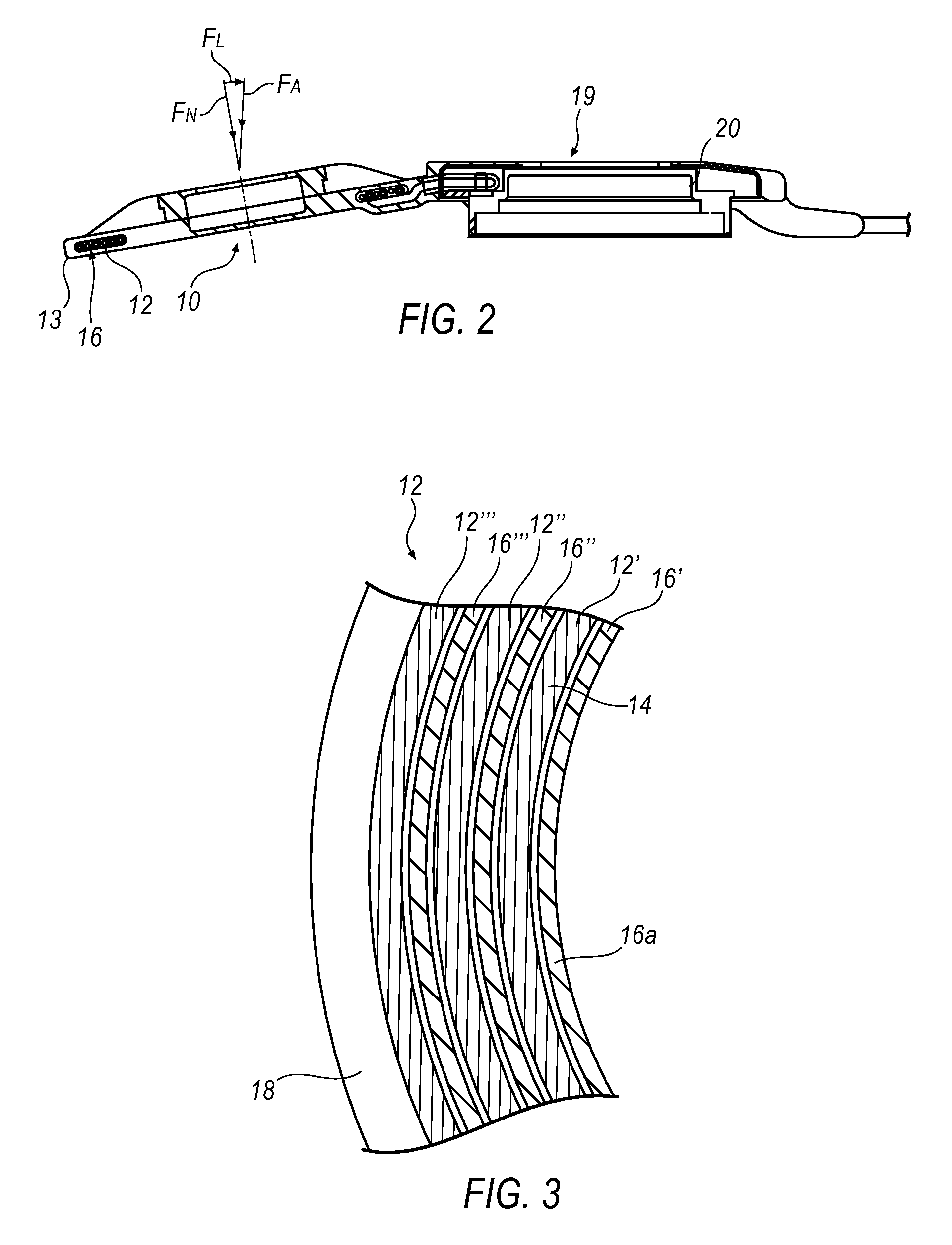
[0035]As illustrated most clearly in FIGS. 7 and 9, the second non-orthogonal force absorbing reinforcement 16 of the antenna coil assembly 10 of the present invention comprises an elongated bundle 16b of longitudinally extending fibers of a polymeric material, such as polyethylene, located in radial outward spaces 16s between the filaments of the wire 14, and polyethylene fibers wound or braided into a longitudinally extending sleeve or jacket 16j receiving and radially confining the wire 14 of the antenna coil 12 within the silicone tube 15 at an inner surface 15s thereof as represented in FIG. 9.
[0036]As depicted in FIG. 7, the elongated bundle 16b separates from the wire 14 of the coil 12 in the turns 12′″ and 12′ between the coil case 13 and the feedthrough case 20. Following that separation, the end 16e″ of the bundle 16b extends longitudinally from turn 12′″ and wraps around the anchoring post 32. Similarly, the end 16e′ of the bundle 16b extends longitudinally from turn 12′ ...
PUM
 Abstract
Description
Claims
Application Information