Mosaic extremity protection system with transportable solid elements

a protection system and solid element technology, applied in the field of composite material protection systems, can solve the problems of reducing affecting the spherical strength of the mosaic extremity, so as to improve the mobility and comfort, the degree of bending flexure is greater, and the system deflection is more than the effect of impa

Inactive Publication Date: 2014-12-18
WARWICK MILLS INC
View PDF138 Cites 8 Cited by
  • Summary
  • Abstract
  • Description
  • Claims
  • Application Information

AI Technical Summary

Benefits of technology

[0012]The term spall cover or just “cover” used as a noun refers to a first or outer layer of a panel of the invention, such as an elastic knit layer covering the strike-face of the SE layer. The cover provides protection during ordinary usage and contains spall during strike events. “SE layer” refers to at least one layer of very hard SE elements and EB edge members arranged in a matrix or pattern that in conjunction with a flexible backing layer provides a suitable degree of flexibility to an otherwise very hard, strike resistant layer. A fold line in the context of the invention can be loosely defined as a straight line of EB's bisecting an array of SE's; but recognizing that there is actually an axis of flexure coincident with an SE interface or gap on each side of each line of EB's, where the EB mates with its abutting SE's. The term flex backer or just “backer” refers to a flexible backing layer such as a wovens layer, which by use of an adhesive matrix, bonds all the SE and EB parts together. The term “fiber pack” refers to a multi-layered assembly of loose woven or unidirectional fabric components that backs up the primary ballistic protection in a manner further described below. It is intended to further absorb and dissipate the remaining forward energy of the integrated mass and materials that pierce the preceding layers.
[0053]The present invention is a method for designing and fabricating an armor system for protection of a user against a strike by a specified maximum threat ballistic projectile. The method includes specifying a maximum threat ballistic projectile strike against which the user is to be protected, providing a plurality of solid elements, providing a supporting structure, said supporting structure including a flexible backer fabric layer, and bonding the plurality of solid elements to the flexible backer fabric layer using an adhesive bonding matrix that will maintain the plurality of solid elements in a flexible planar array, the flexible planar array having a strike side and a back side, the supporting structure and solid elements being selected and configured to have material properties that cause an impacted solid element to be dislodged from said planar array upon impact thereupon by the maximum threat ballistic projectile strike, and to combine substantially all of its mass with the mass of the maximum threat ballistic projectile, thereby providing a reduced velocity and an enlarged impact area of the combined solid element and projectile, as compared to a velocity and impact area of the maximum threat ballistic projectile alone, and the flexible backer fabric layer being selected and configured to have material properties causing it to fail in tensile and to allow the combined maximum threat ballistic projectile and impacted solid element to pass through the flexible backer fabric layer before the maximum threat ballistic projectile has fully penetrated the impacted solid element.

Problems solved by technology

Design factors in body armor include fiber durability, laminate durability, performance variability in large ceramic plates and low design margins that all contribute to reliability issues.
Other specification issues include: cost, density and total system mass, flexibility, mobility, heat retention, and integration with load carrying systems.
Porosity severely degrades the ballistic properties of ceramic armor as it acts as a crack initiator, and unfortunately, B4C has historically not sintered well.
Sintering aids, e.g. graphite, improve sintering but degrade hardness and ballistic properties.
However, commercial hot pressing requires nesting of parts, which restricts the shape of the parts to plates or simple curves.
Traditional systems with overlapping armor elements have not been able to provide the sought-after degree of flexure with the required continuous protection across fold lines of the garment or panel.
Moreover, overlapping ceramic systems suffer from very high mass per unit area, which translates into weight in the protective panel or garment.

Method used


Image

  • Mosaic extremity protection system with transportable solid elements
  • Mosaic extremity protection system with transportable solid elements
  • Mosaic extremity protection system with transportable solid elements

Examples


example 1

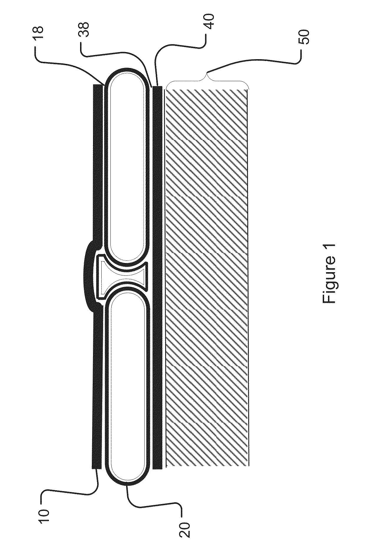
[0122]B4C ceramic of at least 99.5% density is wrapped with six plies of four-layer Dyneema UDPE tape. The ceramic is 5 mm thick with a 50 mm square format. The edge bars have a full radius undercut to their T profile matching the wrapped thickness and edge profile of the SE. The EB is 8 mm high and has the same wrap as the SE component. The spall cover is two layers of 6 oz / yd2 knit lycra-nylon material bonded to the face of the SE wrap with Loctite 3030 PE grade low temperature adhesive. The flex backer is four plys of 3 oz / yd2 840 Denier / 70 / 2 staple composite fabric bonded with a cement coating of AC grade Neoprene. The underside SE wrap is bonded to the flex backer with the same Loctite adhesive. The fiber pack consists of up to 1.5 lb / ft2 of Dyneema shield material in combination with the composite yarn Twarron woven in the 1 / 3-1 / 3-1 / 3 configuration with UDPE materials on the outer faces.

[0123]This and similar embodiments may have a construction sequence as follows. The solid e...

example 2

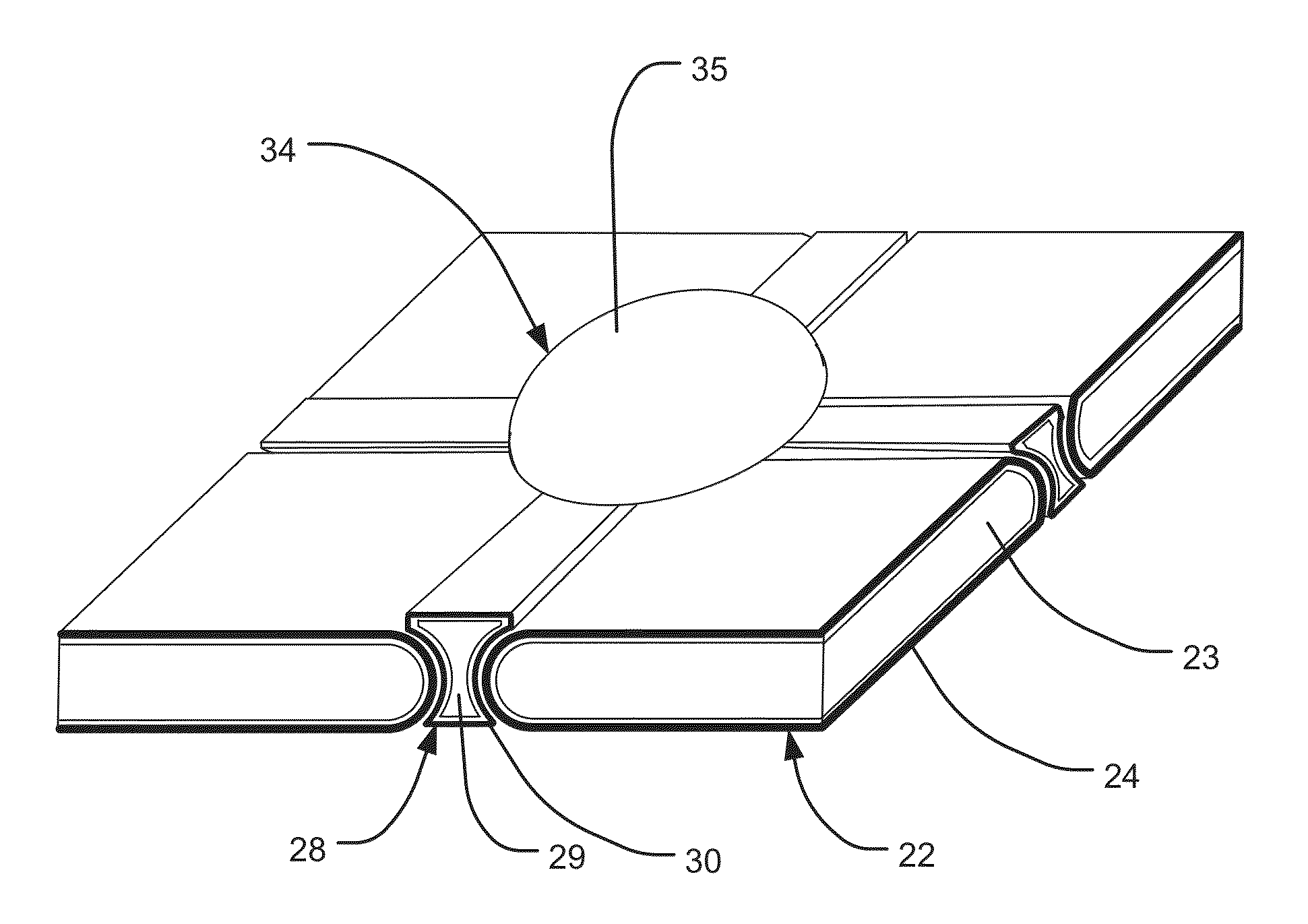
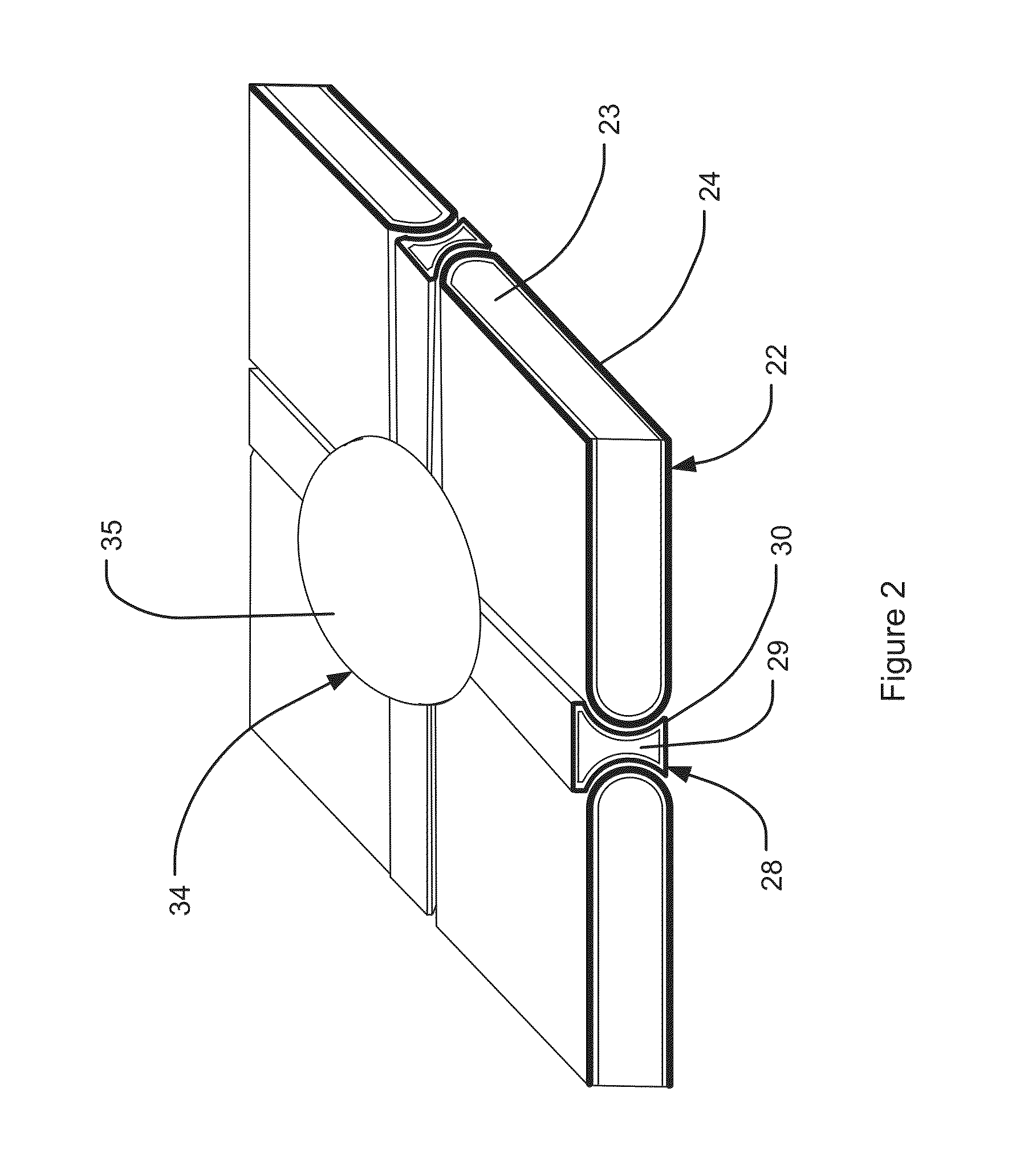
[0130]Another example of the invention uses ceramic-fiber solid element SEs that are three sided, 50 mm on a side. The slightly crowned ceramic core has a 6 mm dome height and an actual thickness of 5 mm. The SE / EB joint has a gap / height ratio of less than 25%. The ceramic core is of B4C material, TCE pre-stressed. The edge bars EB have the three facet end cut or face of FIG. 3, a T cross section profile size of 9 mm high and 9 mm wide, and are made of B4C ceramic. The center buttons CB are 20 mm diameter, 11 mm high at the domed top, including a shank that is 10 mm long, and are made of B4C ceramic. The rigid fiber covering wrap on all components consists of PBO 500 denier woven 5-10 ply material and high modulus epoxy B stage materials. The wrap is 1.5 mm thick. The flex backer is of an aramid-elastomeric design using three to twelve layers of 840d composite yarn fabric. The system mass at this point is about 5 lb / ft2. The fiber pack consists of wovens and / or unidirectional fiber ...

example 3

[0131]Another example of the invention uses square ceramic-fiber solid elements (SE), the outer layer or wrap of which is a fiber laminate. The SEs are 75 mm on a side, of 5 mm thickness, after a steel containment layer is brazed to the ceramic core. The SE core material is of B4C material with TCE compression. The SE / EB / SE interfaces have a contact interface or zero gap, at zero degrees of flexure. The edge bars have a slightly domed T cross section profile 8 mm wide×9 mm high and are made of B4C material. The center button is 20 mm diameter and 10 mm high with its domed top, and make of B4C material. The rigid fiber cover wrap is of PBO material, 500 denier woven, five to ten plys, and uses high modulus epoxy B stage materials. The flex backer is of an aramid-elastomer construction, using three to twelve layers of 840 maximum denier composite yarn fabric. The fiber pack is as described in the prior example.


PUM

PropertyMeasurementUnit
elongationaaaaaaaaaa
lengthaaaaaaaaaa
lengthaaaaaaaaaa

Abstract

A method of protecting a user from a strike by a maximum threat includes adhesively bonding a plurality of solid elements to a support structure in a planar array, dimensions and material properties of the solid elements, support structure, and adhesive being selected to cause an impacted solid element to be dislodged by the maximum threat, and to combine its mass with the projectile for reduced velocity and increased impact area. The support structure is configured to fail in tensile and to allow the combined projectile and solid element to pass through the support structure. The solid elements can be ceramic, and can be commutated upon impact while remaining substantially intact. The solid elements can include titanium backing layers. After formation, ceramic cores can be compressed upon cooling by an outer ceramic layer having a higher coefficient of thermal expansion, the outer layer being formed by glazing or doping.

Description

RELATED APPLICATIONS[0001]This application is a continuation of co-pending application Ser. No. 12 / 902,285, filed on Oct. 12, 2010. Application Ser. No. 12 / 902,285 is a continuation in part of application Ser. No. 11 / 742,705 filed May 1, 2007, which issued as U.S. Pat. No. 7,874,239 on Jan. 25, 2011. Application Ser. No. 11 / 742,705 claims the benefit of U.S. Provisional Application Nos. 60 / 796,440 filed May 1, 2006, and 60 / 837,098 filed Aug. 11, 2006. Each of these applications is herein incorporated by reference in its entirety for all purposes.STATEMENT OF GOVERNMENT INTEREST[0002]Portions of the present invention may have been made in conjunction with Government funding under contract number W911QY-06-C-0105, and there may be certain rights to the Government.FIELD OF INVENTION[0003]This invention relates to protective systems for shielding human users from strikes by selected types of penetrators, and in particular to composite material systems providing adequate flexibility for ...

Claims


Application Information

Patent Timeline
Patent Type & Authority Applications(United States)
IPC IPC(8): F41H1/02B32B37/12F41H5/04
CPCF41H1/02F41H5/0471F41H5/0435B32B2307/542B32B37/12B32B2323/04B32B2313/02F41H5/0457F41H5/0428F41H5/0492Y10T156/1092Y10T156/1093
Inventor HOWLAND, CHARLES A.
Owner WARWICK MILLS INC
Why Eureka
Try Eureka