Spray bottle reservoir system

a reservoir system and spray bottle technology, applied in the field of spray bottle reservoir systems, can solve the problems of potential financial loss, limited user's range of orientations to effectively utilize the contained fluid, and the tube inside the bottle is not ideal for extracting the remaining fluid,

Active Publication Date: 2012-12-04
GIOIA CONSTANTINE M
View PDF14 Cites 14 Cited by
  • Summary
  • Abstract
  • Description
  • Claims
  • Application Information

AI Technical Summary

Benefits of technology

[0006]The spray bottle reservoir system includes a bottle having a neck and a body, the body defining a main chamber for containing fluid. A spray cap is detachably mounted to the neck. A vertical partition is disposed inside the body, separating the main chamber to form a dispensing reservoir. A dip tube extends from the spray cap to the bottom of the dispensing reservoir. The dispensing reservoir may be refilled from the remaining chamber and, due to the relative small volume of the dispensing reservoir and the viscosity of the fluid, the dispensing reservoir permits maximum consumption of the fluid in a wide range of spraying positions.

Problems solved by technology

While these conventional bottles work well to dispense the fluid, they do not consume the last couple of ounces or dregs from the bottom of the bottle due, in part, to the dip tube not being capable of reaching the remaining fluid, e.g., the tube is not long enough and / or the placement of the tube inside the bottle is not ideal for extraction of the remaining fluid.
For budget minded consumers, that is a potential financial loss over time.
In addition, these bottles with the remaining fluid are often discarded, which creates additional and avoidable waste.
However, such a configuration limits the range of orientations for the user to effectively utilize the contained fluid.

Method used


Image

  • Spray bottle reservoir system
  • Spray bottle reservoir system
  • Spray bottle reservoir system

Examples


Embodiment Construction

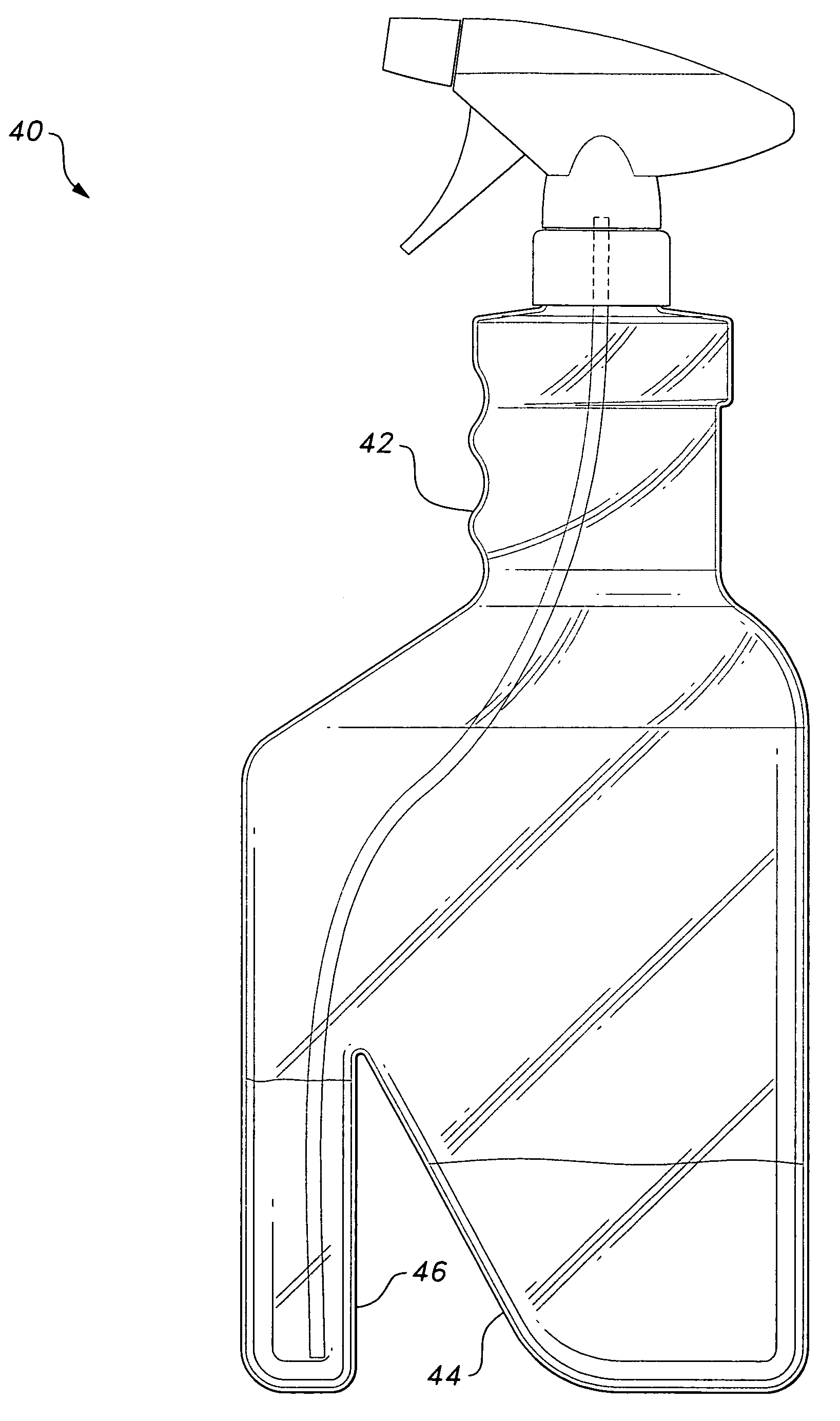
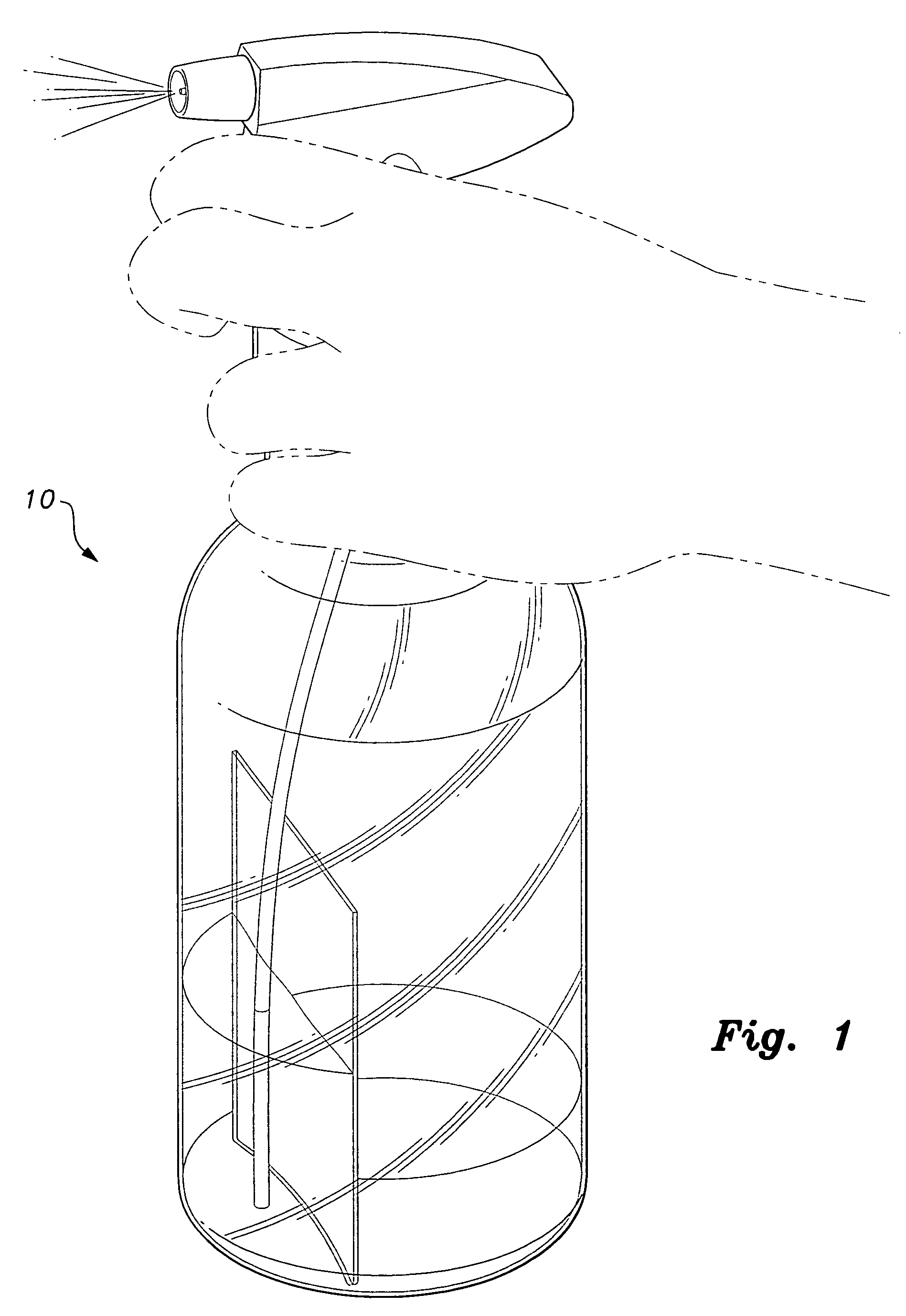
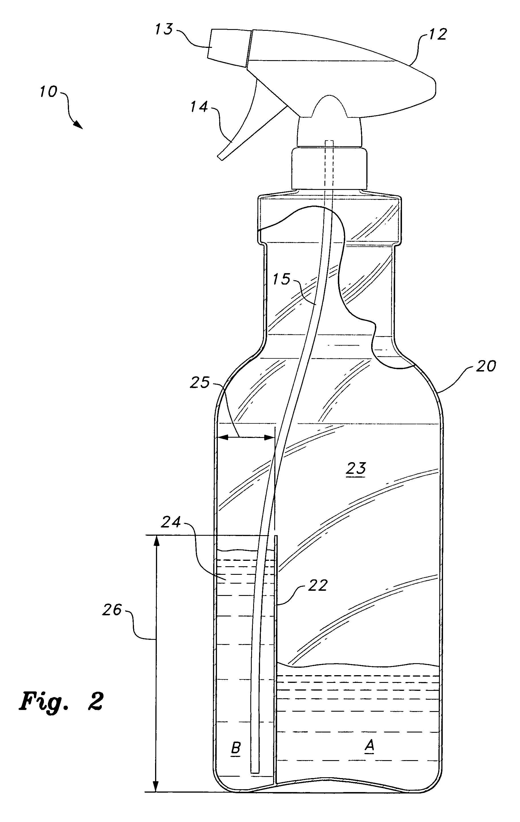
[0016]The present invention relates to a spray bottle reservoir system 10 with features that permit maximum consumption of the dispensing fluid contained in the bottle in a wide range of spraying positions. Referring to FIGS. 1 and 2, the spray bottle reservoir system 10 includes a spray head or cap 12 attached to the neck of a bottle 20. The spray cap 12 includes a nozzle 13 through which fluid or liquid A, B is dispensed. A source or dip tube 15 extends from the spray cap 12 into the main chamber 23 of the bottle, and the trigger 14 pumps the fluid A, B to be sprayed out the nozzle 13.

[0017]To maximize consumption of the fluid A, B, the spray bottle reservoir system 10 includes a vertically oriented partition or wall 22 disposed in the interior main chamber 23, dividing the main chamber and forming a dispensing reservoir 24. The volume of the dispensing reservoir 24 is relatively smaller than the overall volume of the bottle or container 20, and the dispensing reservoir volume may...


PUM


Abstract

The spray bottle reservoir system includes a bottle having a neck and a body, the body defining a main chamber for containing fluid. A spray cap is detachably mounted to the neck. A vertical partition is disposed inside the body, separating the main chamber to form a dispensing reservoir. A dip tube extends from the spray cap to the bottom of the dispensing reservoir. The dispensing reservoir may be refilled from the remaining chamber, and due to the relative small volume of the dispensing reservoir and the viscosity of the fluid, the dispensing reservoir permits maximum consumption of the fluid in a wide range of spraying positions.

Description

CROSS-REFERENCE TO RELATED APPLICATION[0001]This application claims the benefit of U.S. Provisional Patent Application Ser. No. 61 / 213,002, filed Apr. 27, 2009.FIELD OF THE INVENTION[0002]The present invention relates to fluid dispensers, more specifically, to a spray bottle reservoir system configured to maximize usage of the fluid therein.DESCRIPTION OF THE RELATED ART[0003]Spray bottles or fluid dispensers are convenient devices for dispensing fluids for cleaning, gardening, pest control and a variety of other daily chores or activities. One of the main concerns with spray bottles relates to the efficient consumption of the liquid stored therein. Most conventional spray bottles include a spray cap detachably mounted to the neck of a bottle with a dip tube or source line extending from the spray head into the body of the bottle. The fluid inside the bottle is pumped or drawn through the dip tube and out of the nozzle of spray head. While these conventional bottles work well to dis...

Claims


Application Information

Patent Timeline
Patent Type & Authority Patents(United States)
IPC IPC(8): B67D7/58
CPCB05B11/0037B05B11/3047B05B15/005B05B11/3011B65D83/32B05B15/30B05B11/1011B05B11/1047
Inventor GIOIA, CONSTANTINE M.
Owner GIOIA CONSTANTINE M
Why Eureka
Try Eureka