Robot vision system and detection method

a robot vision and detection method technology, applied in the field of robot vision systems and detection methods, can solve the problems that conventional techniques cannot be cannot be directly applied to movable robot applications, etc., and achieve the effects of increasing the idle time and reducing the cost of the movable robo

Inactive Publication Date: 2012-12-11
ELECTRONICS & TELECOMM RES INST
View PDF10 Cites 4 Cited by
  • Summary
  • Abstract
  • Description
  • Claims
  • Application Information

AI Technical Summary

Benefits of technology

[0025]In the movable robot vision system that outputs an original images and a disparity map of the stereo camera according to the present invention, the movable robot vision system can discover a person who waves his or her hand or moves in front of the robot in order to attract a robot's attention and determine an obstacle in front of the person only with relatively low computational complexity, thereby less consuming a main processor and a battery and increasing an idle time of the movable robot.
[0026]In the movable robot vision system that outputs an original images and a disparity map of the stereo camera according to the present invention, the movable robot can simply detect a location of a person and approach a moving person while avoiding obstacles. Accordingly, a networked movable robot system does not have to send an image to a server all through the idle time, thus reducing network traffic and increasing the availability of the server.
[0027]In the movable robot vision system that outputs an original images and a disparity map of the stereo camera according to the present invention, even when a robot server is unavailable due to temporarily excessive traffic or due to network disconnection caused by the robot passing through a dead spot while tracking a person, the robot terminal itself can continue to track a person and move to a network available region, thus continuously providing service.

Problems solved by technology

However, because such cameras are fixed and operate under an assumption that a background is not greatly changed within a short time, conventional techniques cannot be applied to movable robot applications in which a view is continuously changed whenever a movable robot moves or interacts with a person.
Because the technology is used for dividing a foreground and a background more accurately and, thereby, reducing data, it cannot be directly applied to movable robot applications in which a view is continuously changed whenever a movable robot moves or interacts with a person.

Method used


Image

  • Robot vision system and detection method
  • Robot vision system and detection method
  • Robot vision system and detection method

Examples


Embodiment Construction

[0041]Hereinafter, preferred embodiments of the present invention will be described in detail with reference to the accompanying drawings so that they can be readily implemented by those skilled in the art.

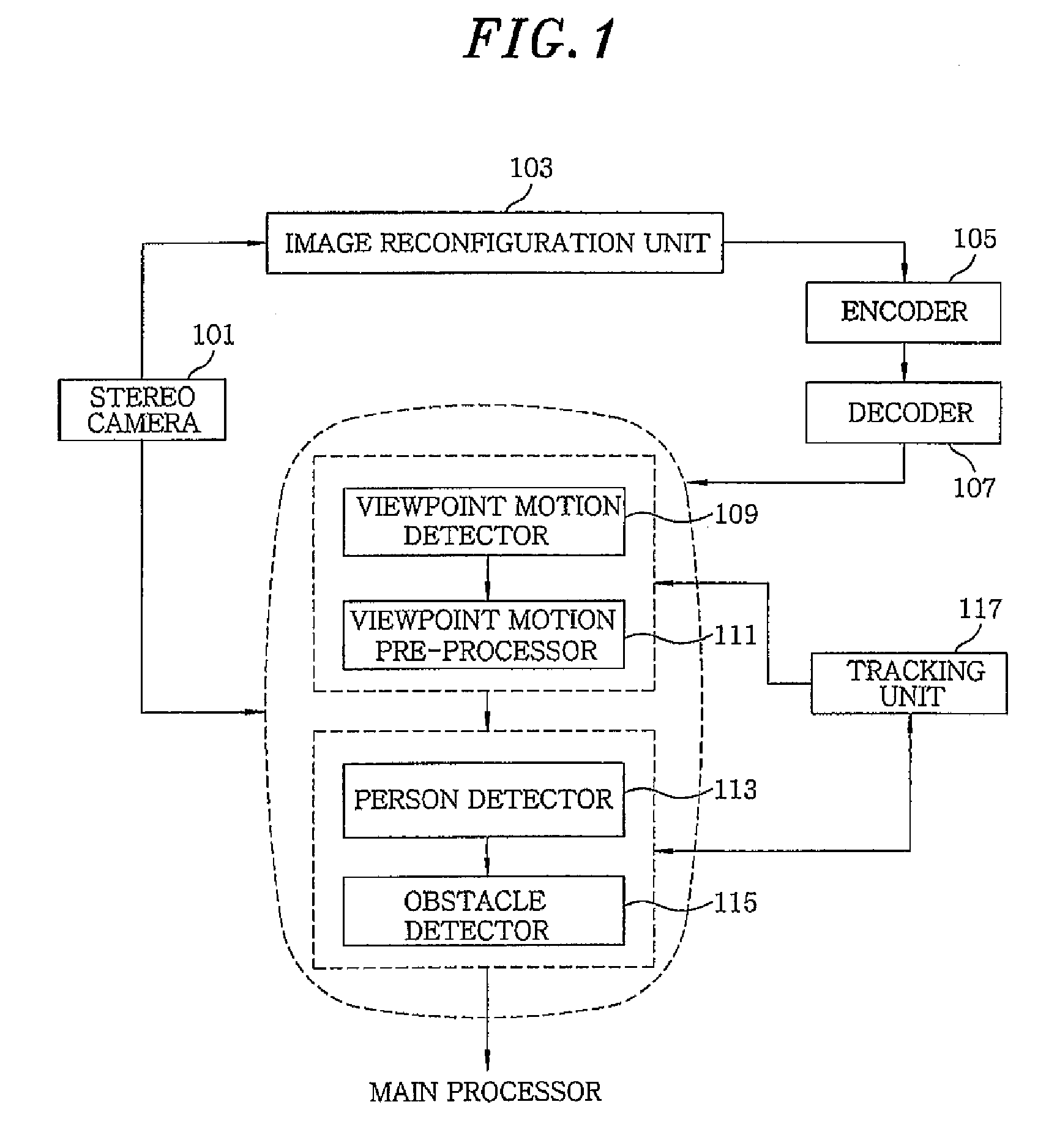
[0042]FIG. 1 is a block diagram illustrating a robot vision system for detecting a person and obstacles during a motion in accordance with a preferred embodiment of the present invention. The robot vision system includes a stereo camera 101, an image reconfiguration unit 103, an encoder 105, a decoder 107, a viewpoint motion detector 109, a viewpoint motion pre-processor 111, a person detector 113, and an obstacle detector 115.

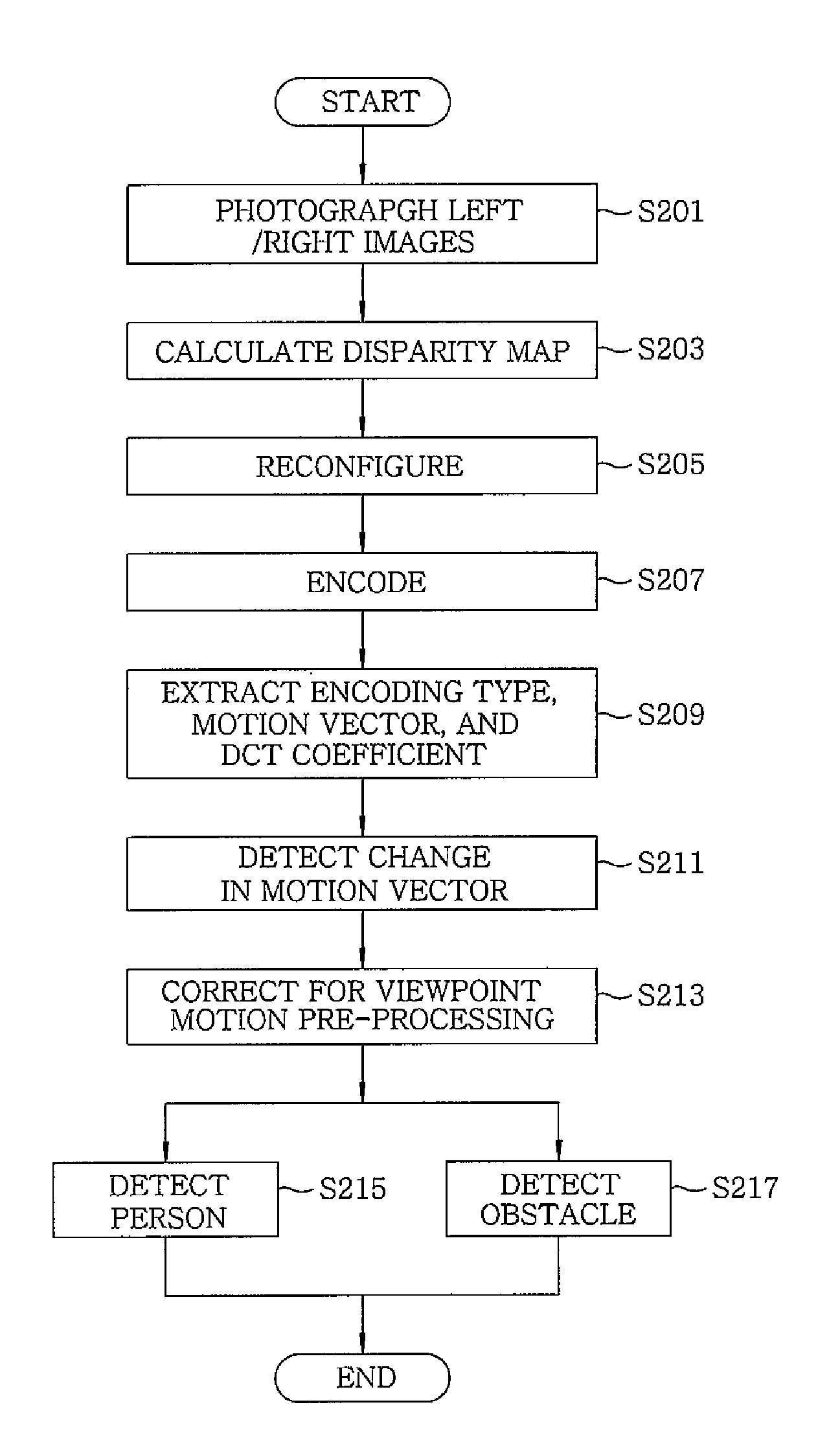
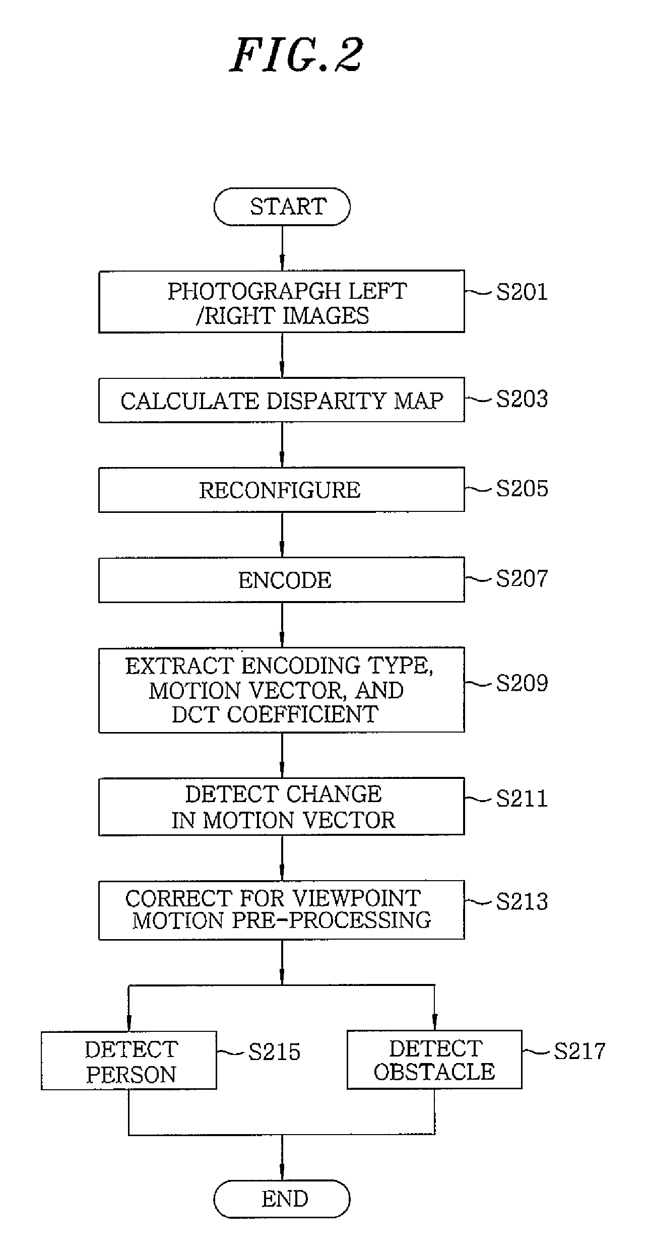
[0043]The stereo camera 101 photographs a left view image of the robot using a left camera and a right view image of the robot using a right camera, calculates a disparity map (e.g., a disparity image between the left and right images), which is related to a difference between the two images, provides the left view image and the right view image to the image...


PUM


Abstract

A robot vision system for outputting a disparity map includes a stereo camera for receiving left and right images and outputting a disparity map between the two images; an encoder for encoding either the left image or the right image into a motion compensation-based video bit-stream; and a decoder for extracting an encoding type of an image block, a motion vector, and a DCT coefficient from the video bit-stream. Further, the system includes a person detector for detecting and labeling person blocks in the image using the disparity map between the left image and the right image, the block encoding type, and the motion vector, and detecting a distance from the labeled person to the camera; and an obstacle detector for detecting a closer obstacle than the person using the block encoding type, the motion vector, and the DCT coefficient extracted from the video bit-stream, and the disparity map.

Description

CROSS-REFERENCE(S) TO RELATED APPLICATIONS[0001]The present invention claims priority of Korean Patent Application No. 10-2007-0113682, filed on Nov. 8, 2007, which is incorporated herein by reference.FIELD OF THE INVENTION[0002]The present invention relates to a robot vision system and a detection method, and more particularly, to a movable robot vision system that outputs an original image and a disparity map of a stereo camera and a detection method that are capable of approaching a moving person while avoiding obstacles.[0003]This work was supported by the IT R&D program of MIC / IITA. [2005-S-033-03, Embedded Component Technology and Standardization for URC]BACKGROUND OF THE INVENTION[0004]As known, a conventional movable robot uses ultrasonic sensors or infrared sensors for sensing a distance to obstacles, as well as a camera for having a conversation with a person.[0005]Several sensors of the same type, each having a highly limited sensing range, must be mounted around the robo...

Claims


Application Information

Patent Timeline
Patent Type & Authority Patents(United States)
IPC IPC(8): G06K9/00G06K9/46
CPCG06K9/00664G06T7/0075H04N7/18G06T2207/10021G06T2207/20021G06T2207/20052G06T2207/30196G06T2207/30261G06T7/593G06V20/10G05D1/02
Inventor LIM, EUL GYOONCHO, JAE ILHWANG, DAE HWAN
Owner ELECTRONICS & TELECOMM RES INST
Why Eureka
Try Eureka