System and method for forming serial numbers on hdd wafers

Inactive Publication Date: 2006-11-02
WESTERN DIGITAL TECH INC
View PDF15 Cites 2 Cited by
  • Summary
  • Abstract
  • Description
  • Claims
  • Application Information

AI Technical Summary

Benefits of technology

[0005] Embodiments of the invention describe methods for creating serial numbers on devices using optical lithography and processes. The serial numbers thus created are unique to every slider device fabricated: a unique within-wafer component distinguishes between devices on a given wafer, while a unique wafer-number component distinguishes between similarly-located devices on different wafers. The optical printing technique described herein has several advantages over current methods of serialization. First, cost is reduced. Secon

Problems solved by technology

Second, the resolution capability of optical methods and processing allows for the creation of sm

Method used


Image

  • System and method for forming serial numbers on hdd wafers
  • System and method for forming serial numbers on hdd wafers
  • System and method for forming serial numbers on hdd wafers

Examples


Embodiment Construction

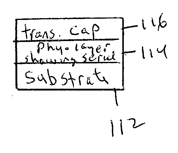
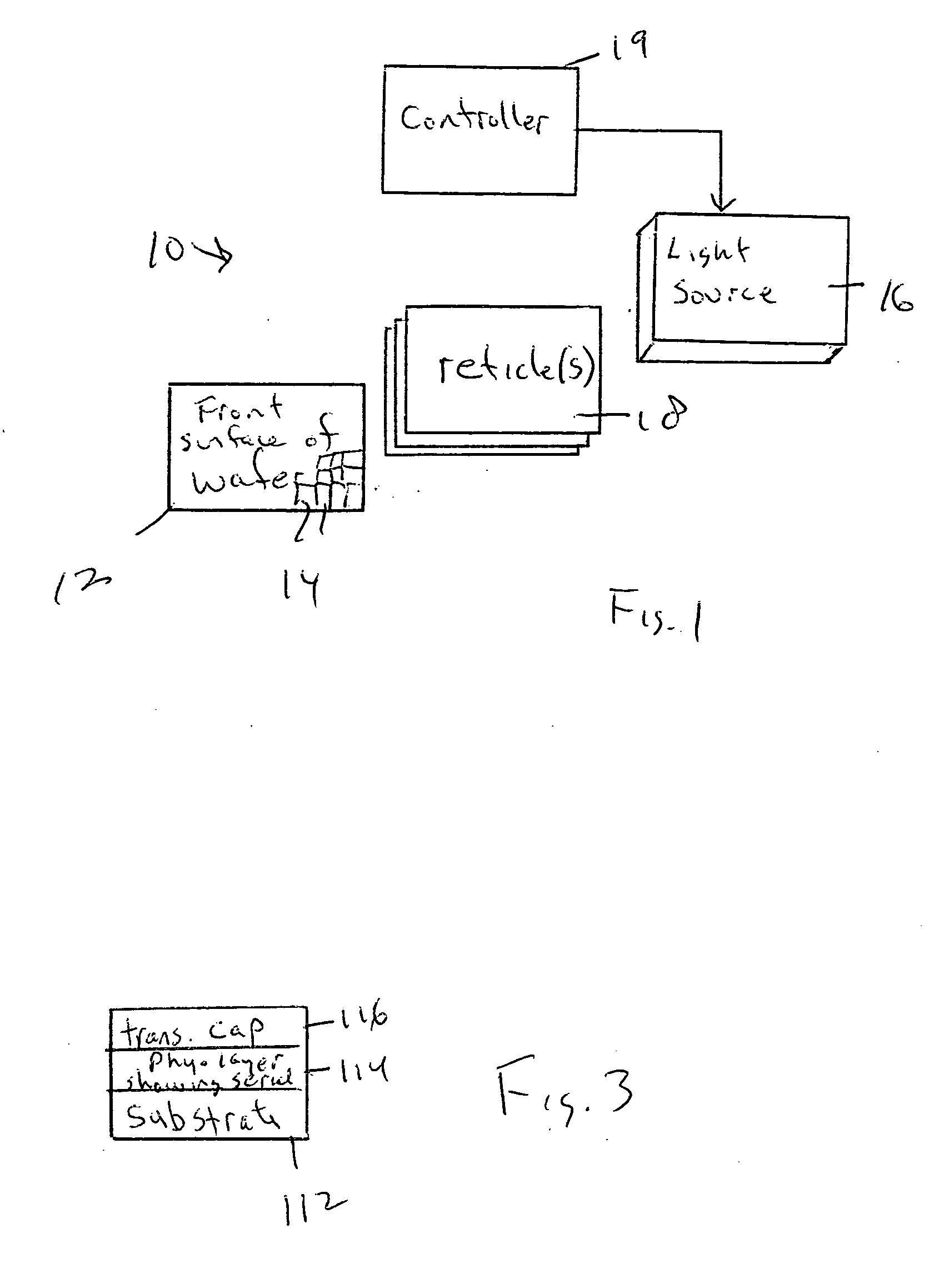
[0016] Referring initially to FIG. 1, a system is shown, generally designated 10, in which the front surface of a wafer 12 bearing plural slider regions 14 is illuminated by light from a light source 16 passing through a set of reticles 18. The light source 16 and / or reticles 18 and / or wafer 12 are controlled by a controller 19 having a core processor and memory such as but not limited to solid state or disk memory for executing at least portions of the logic of FIG. 2. The controller 19 may be referred to as a “stepper” or “optical stepper”. By “set” of reticles is meant one or more optical reticles configured in accordance with optical photoresist principles in the semiconductor art. As set forth further below, the controller 19 controls the energization of the light source 16 and / or the position of the reticles 18 relative to the wafer 12 to form numbers on the front surface of the wafer 12 that indicate both the serial number of the particular wafer 12 itself, as well as indicia...


PUM

PropertyMeasurementUnit
Transparencyaaaaaaaaaa

Abstract

Both the wafer serial number and slider region location indicia on the wafer are formed on the front surface of the wafer using optical principles, i.e., without using a laser.

Description

[0001] This application claims priority from U.S. provisional patent application Ser. No. 60 / 676,630, filed May 9, 2005.I. FIELD OF THE INVENTION [0002] The present invention relates generally to devices created by wafer processing, such as micromachines and semiconductors, and more particularly to controller chips for hard disk drives. II. BACKGROUND OF THE INVENTION [0003] Read / write head structures colloquially known as “sliders” typically are manufactured in groups on a semiconductor wafer. To track individual sliders, heretofore indicia representing each slider's position on the wafer have been optically formed on the “front” of the wafer next to each slider, while a serial number representing the wafer has been formed by laser projection or etching on the “back” surface of the slider. Such tracking a necessary for, e.g., process control, to ascertain for instance whether sliders at a particular wafer position wafer-to-wafer are being defectively made, or whether a particular w...

Claims


Application Information

Patent Timeline
IPC IPC(8): G03F1/00
CPCG03F1/14Y10T29/49041H01L23/544G03F1/00H01L2924/0002H01L2924/00
Inventor GURUZ, UNAL MURATGUTBERLET, MARY KATHRYNWERNER, DOUGLAS JOHNSONNGA WINTON, YVETTE CHUNG
Owner WESTERN DIGITAL TECH INC
Why Eureka
Try Eureka