
Enclosed-channel reactor system and method to manufacture catalysts or support

a reactor system and closed-channel technology, applied in the direction of physical/chemical process catalysts, metal/metal-oxide/metal-hydroxide catalysts, cell components, etc., can solve the problems of low utilization efficiency of catalysts grown by conventional vapor deposition processes, and difficult to uniformly deposit catalysts or supports on channel surfaces with good dispersion. , to achieve the effect of improving coating uniformity and less precursor consumption

Active Publication Date: 2014-05-22
NAT APPLIED RES LAB
View PDF5 Cites 3 Cited by
  • Summary
  • Abstract
  • Description
  • Claims
  • Application Information

AI Technical Summary

Benefits of technology

The present invention is a method for improving coating uniformity by using a vapor deposition technique with a capping mechanism. This technique involves directing precursors and purge gas through the inner path of an enclosed-channel reactor, which results in the consumption of less precursors and improved coating quality. The reactor system consists of a reactor body with multiple channels for catalytic reaction, an enclosure that surrounds the reactor body, and a reactor cap that is either located upstream or downstream of the gas flow. The reactor cap is sealed with an elastomer O-ring to isolate it from the environment. This invention provides a more efficient and effective method for coating a variety of substrates with uniform quality.

Problems solved by technology

However, it is difficult to uniformly deposit the catalyst or support on channel surface with good dispersion due to restriction of channel shape or size and poor precursor liquidity.
However, only a limited amount of catalyst on the surface is available for catalytic reaction so that the utilization efficiency of catalyst is low.
Therefore, the utilization efficiency of catalyst grown by a conventional vapor deposition process would be low.
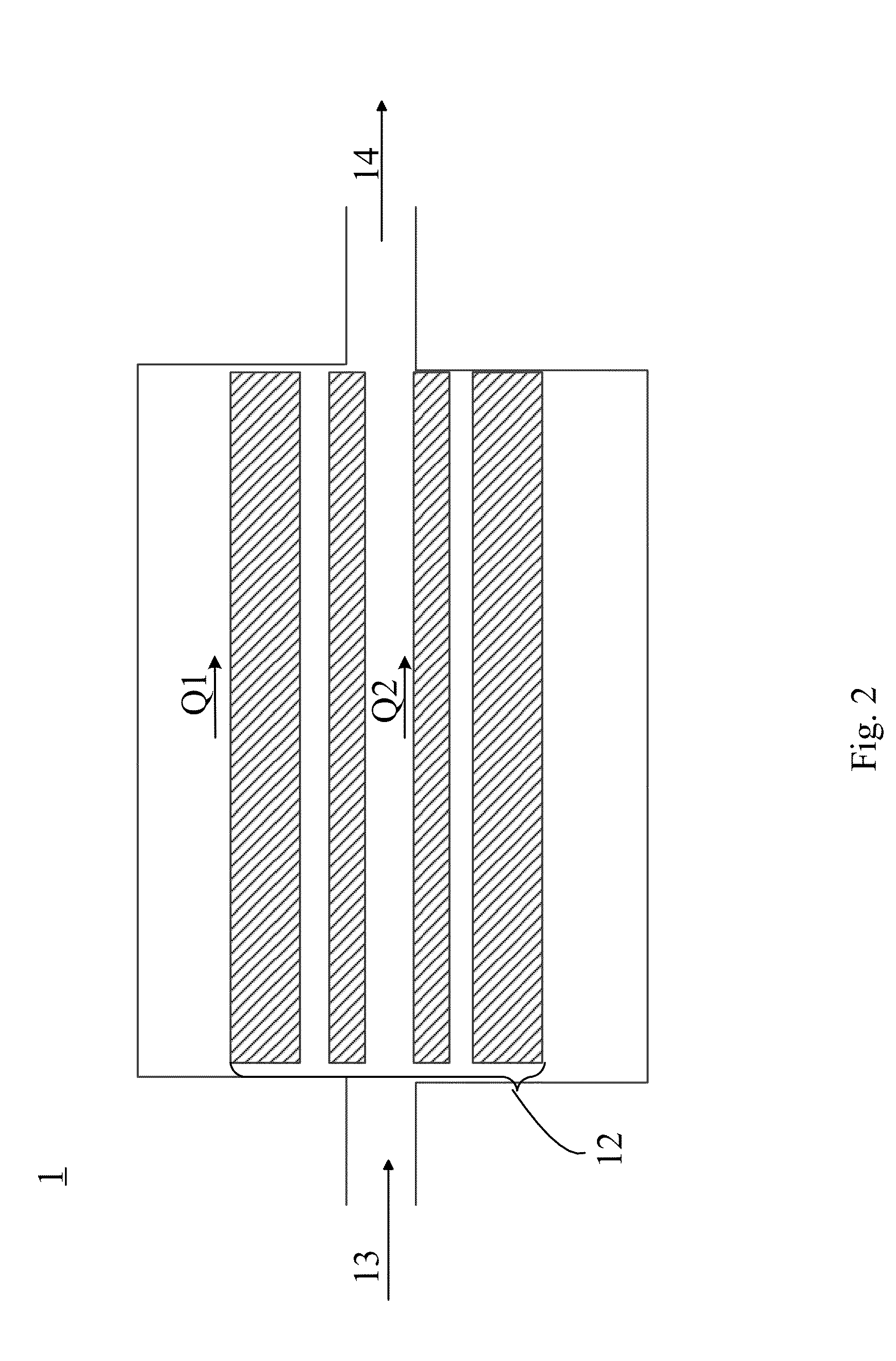
Uses of extended injection duration and high concentration may lead to a thicker coating along path Q2, but the cost would increase significantly.

Method used


Image

  • Enclosed-channel reactor system and method to manufacture catalysts or support
  • Enclosed-channel reactor system and method to manufacture catalysts or support
  • Enclosed-channel reactor system and method to manufacture catalysts or support

Examples


Embodiment Construction

[0025]An enclosed-channel reactor system 2 in the present invention, as shown in FIG. 3, comprises a reactor body 21, an inlet cap 22 and an outlet cap 23. The reactor body 21 with a cylindrical or polygonal contour has a plurality of channels 28 inside, which act as the surface for catalytic reaction. The inlet cap 22 connects with the reactor body 21 at the upstream side 25 of gas flow and has conduit linking to the channels 28. The outlet cap has conduit linking to the channels of reactor body 21 at the downstream side 26 of gas flow and to a vacuum pump on the other side. Both inlet cap 22 and outlet cap 23 contact the reactor body with an elastomer O-ring 24 stuffed into a groove 27 for isolation from the atmosphere, as shown in FIG. 3.

[0026]Another enclosed-channel reactor system 3 in the present invention, as shown in FIG. 4, comprises a reactor body 31, a reactor enclosure 32 and a reactor cap 33. The reactor body 31 with a cylindrical or polygonal contour has a plurality of...


PUM

PropertyMeasurementUnit
Temperatureaaaaaaaaaa
Thicknessaaaaaaaaaa
Ratioaaaaaaaaaa

Abstract

The present invention provides methods and designs of enclosed-channel reactor system for manufacturing catalysts or supports. Both of the configuration designs force the gaseous precursors and purge gas flow through the channel surface of reactor. The precursors will transform to thin film or particle catalysts or supports under adequate reaction temperature, working pressure and gas concentration. The reactor body is either sealed or enclosed for isolation from atmosphere. Another method using super ALD cycles is also proposed to grow alloy catalysts or supports with controllable concentration. The catalysts prepared by the method and system in the present invention are noble metals, such as platinum, palladium, rhodium, ruthenium, iridium and osmium, or transition metals such as iron, silver, cobalt, nickel and tin, while supports are silicon oxide, aluminum oxide, zirconium oxide, cerium oxide or magnesium oxide, or refractory metals, which can be chromium, molybdenum, tungsten or tantalum.

Description

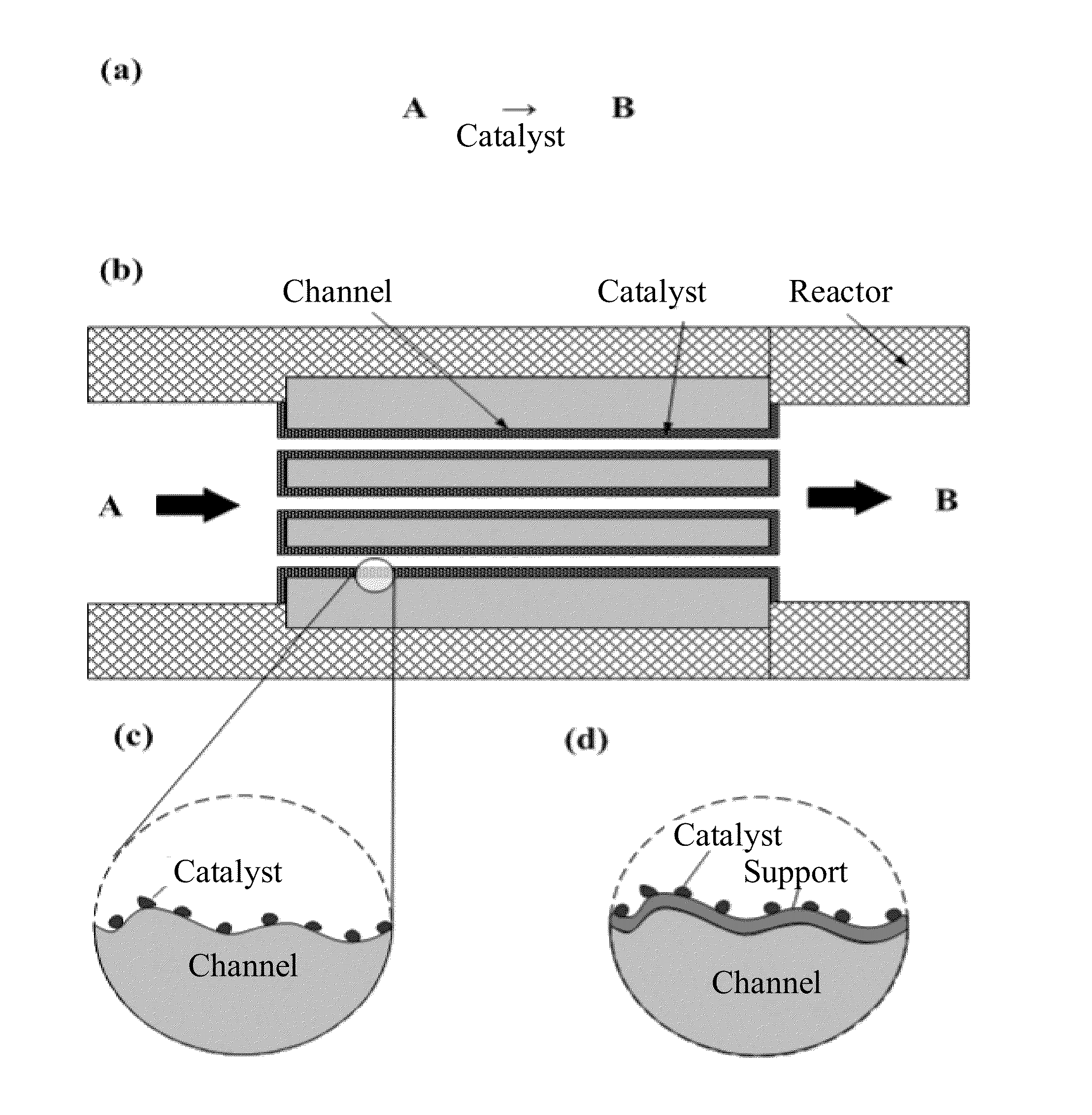
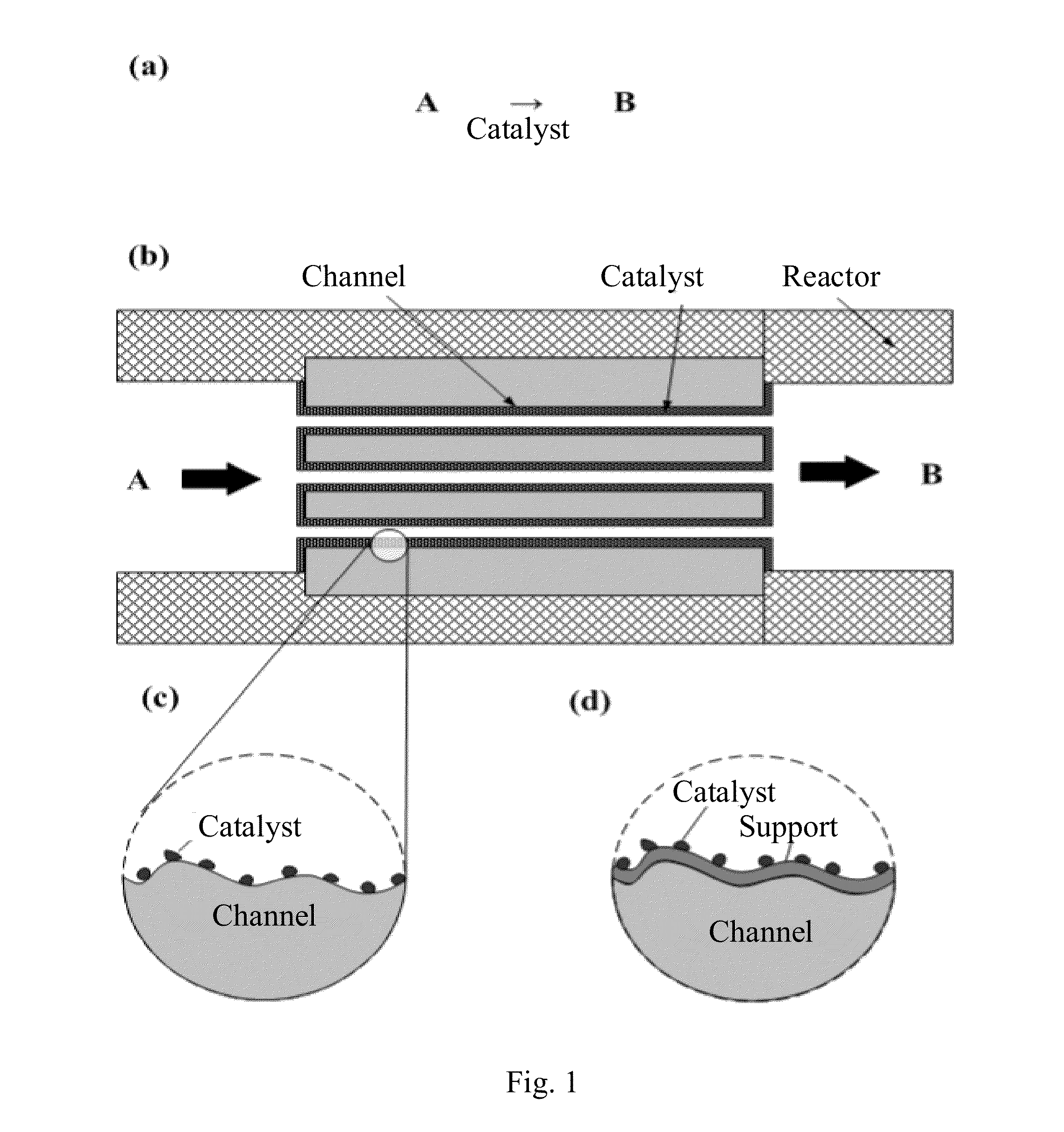
BACKGROUND OF THE INVENTION[0001]1. Field of the Invention[0002]The present invention presents a method based on chemical vapor deposition reactions, particularly an enclosed-channel reactor system and a method to manufacture catalysts or support materials on the basis of atomic layer deposition (ALD).[0003]2. Description of the Prior Art[0004]Catalysts are typically applied to increase reaction rate in various processes with less energy consumption, such as fuel cells and hydrogen production by water splitting. Improving the surface area between gas phase and catalyst would be a key factor to improve the reaction rate. Therefore, to obtain well-dispersed and nanoscaled catalysts with large specific area is crucial for catalytic reactions.[0005]The catalytic reaction can be depicted as shown in FIG. 1(a). With the help of catalyst, reactant A will be transformed to product B in a faster and energy-efficient way. In order to prevent the participation of unwanted elements, the catalyt...

Claims


Application Information

Patent Timeline
IPC IPC(8): B01J35/04B01J37/02
CPCB01J37/0201B01J35/04B01J37/0228B01J37/0244B01J23/14B01J23/38B01J23/42B01J23/462B01J23/50B01J23/74H01M4/9016H01M4/92Y02E60/50B01J35/56B01J37/024
Inventor KEI, CHI-CHUNGLIU, BO-HENGLIN, CHIEN-PAOHSIAO, CHIEN-NANHSUEH, YANG-CHIHPERNG, TSONG-PYNG
Owner NAT APPLIED RES LAB
Learn More