Transmitter circuit, receiver circuit, and transmitting/receiving system

Active Publication Date: 2014-05-22
SK HYNIX INC
View PDF6 Cites 2 Cited by
  • Summary
  • Abstract
  • Description
  • Claims
  • Application Information

AI Technical Summary

Benefits of technology

[0016]According to embodiments of the present invention, since the clock modulated by data is transmitted via one transmission line, the number of lines required to transmit the data may be reduced, and a st

Problems solved by technology

Some transmitting system transmits data without clock and corresponding receiving system recovers a clock included in the data transmitted from the tran

Method used


Image

  • Transmitter circuit, receiver circuit, and transmitting/receiving system
  • Transmitter circuit, receiver circuit, and transmitting/receiving system
  • Transmitter circuit, receiver circuit, and transmitting/receiving system

Examples


Embodiment Construction

[0027]Various exemplary embodiments will be described below in more detail with reference to the accompanying drawings. The present invention may, however, be embodied in different forms and should not be construed as limited to the embodiments set forth herein. Rather, these embodiments are provided so that this disclosure will be thorough and complete, and will fully convey the scope of the present invention to those skilled in the art. Throughout the disclosure, reference numerals correspond directly to the like numbered parts in the various figures and embodiments of the present invention. In addition, a singular form may include a plural form as long as it is not specifically mentioned in a sentence.

[0028]The drawings are not necessarily to scale and in some instances, proportions may have been exaggerated in order to clearly illustrate features of the embodiments.

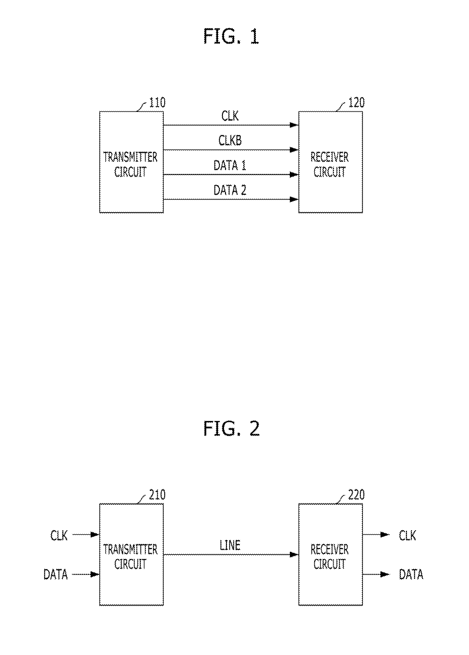
[0029]FIG. 2 is a diagram illustrating the configuration of a transmitting / receiving system in accordance with an e...


PUM


Abstract

A transmitting/receiving system may include a transmission line, a transmitter circuit configured to transmit a clock to the transmission line and to adjust an amplitude of the clock in accordance with a logic level of data, and a receiver circuit configured to receive the clock transferred to the transmission line and to recover the data through detection of the amplitude of the clock.

Description

CROSS-REFERENCE TO RELATED APPLICATIONS[0001]The present application claims priority of Korean Patent Application No. 10-2012-0132965, filed on Nov. 22, 2012, which is incorporated herein by reference in its entirety.BACKGROUND[0002]1. Field[0003]Exemplary embodiments of the present invention relate to a data transmitting / receiving technology.[0004]2. Description of the Related Art[0005]Various integrated circuit chips do not operate alone, but operate to send / receive data with peripheral chips. For example, memory chips, such as a DRAM and a flash memory, send / receive data with a memory controller, and a CPU also sends / receives data with various chips on a motherboard.[0006]FIG. 1 is a diagram illustrating a data transmitting method between a transmitter circuit 110 and a receiver circuit 120 in the related art.[0007]Referring to FIG. 1, the transmitter circuit 110 transmits data DATA1 and DATA2 to the receiver circuit 120 together with clocks CLK and CLKB. Then, the receiver circu...

Claims


Application Information

Patent Timeline
IPC IPC(8): H04L27/06H04L27/04
CPCH04L7/0008H04L25/0264H04L25/03H04L27/066H04L27/04H04L7/02
Inventor LEE, HYUN-WOO
Owner SK HYNIX INC
Why Eureka
Try Eureka