Check patentability & draft patents in minutes with Patsnap Eureka AI!

One-way driver

a one-way driver and driver technology, applied in the field of hand tools, can solve the problems of troublesome disengagement of the rod from the screw, repeated engagement of the rod with the screw,

Active Publication Date: 2012-12-25
CHANG HUI LING
View PDF29 Cites 1 Cited by
  • Summary
  • Abstract
  • Description
  • Claims
  • Application Information

AI Technical Summary

Benefits of technology

The solution simplifies the process of tightening screws by allowing the shaft to engage and disengage efficiently, reducing user effort and improving handling.

Problems solved by technology

The repeated engagement of the rod with the screw and disengagement of the rod from the screw is troublesome.

Method used


Image

  • One-way driver
  • One-way driver
  • One-way driver

Examples


Embodiment Construction

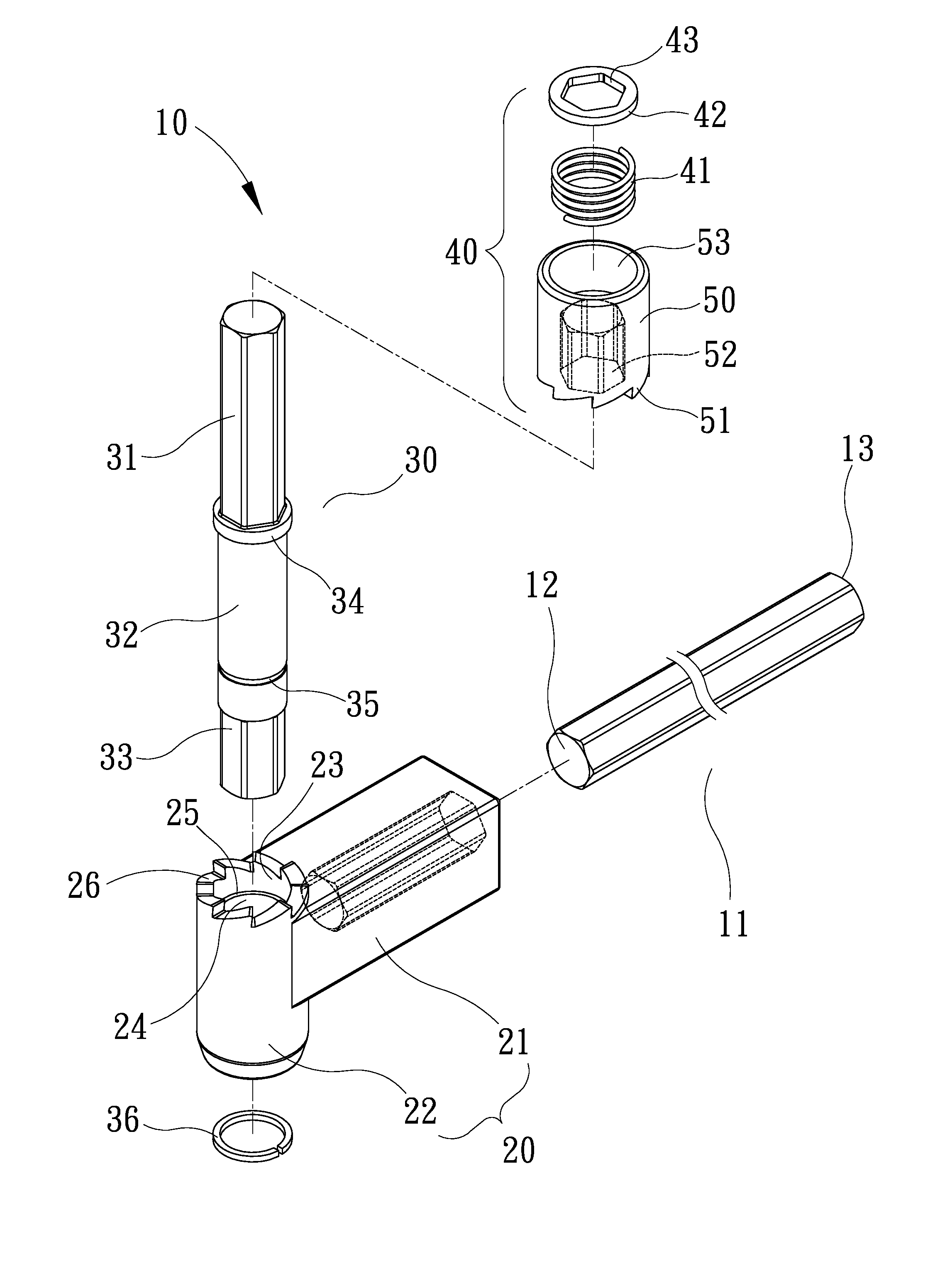
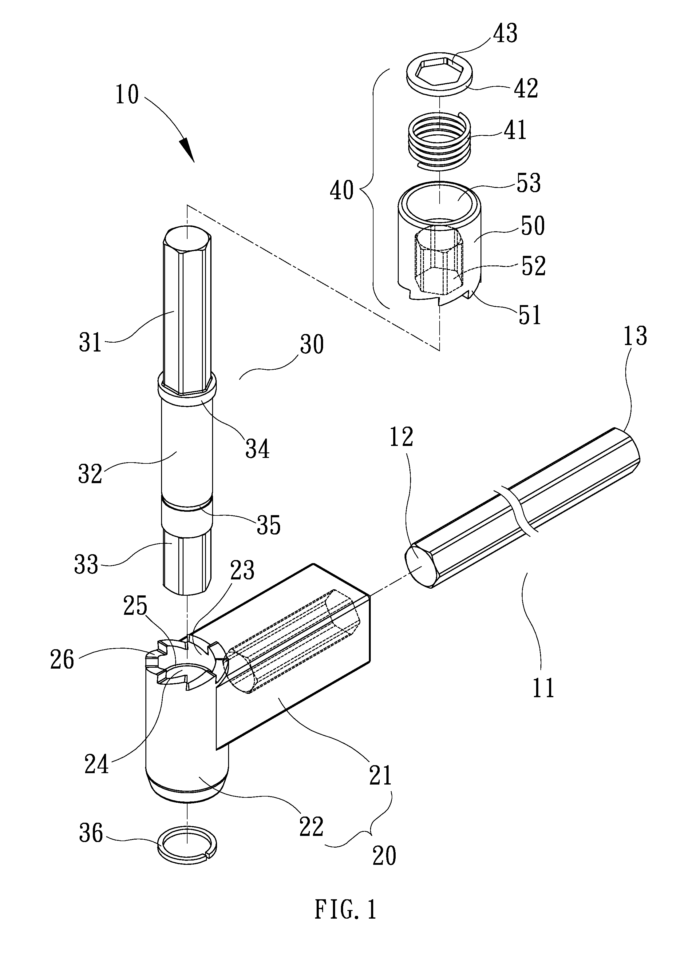
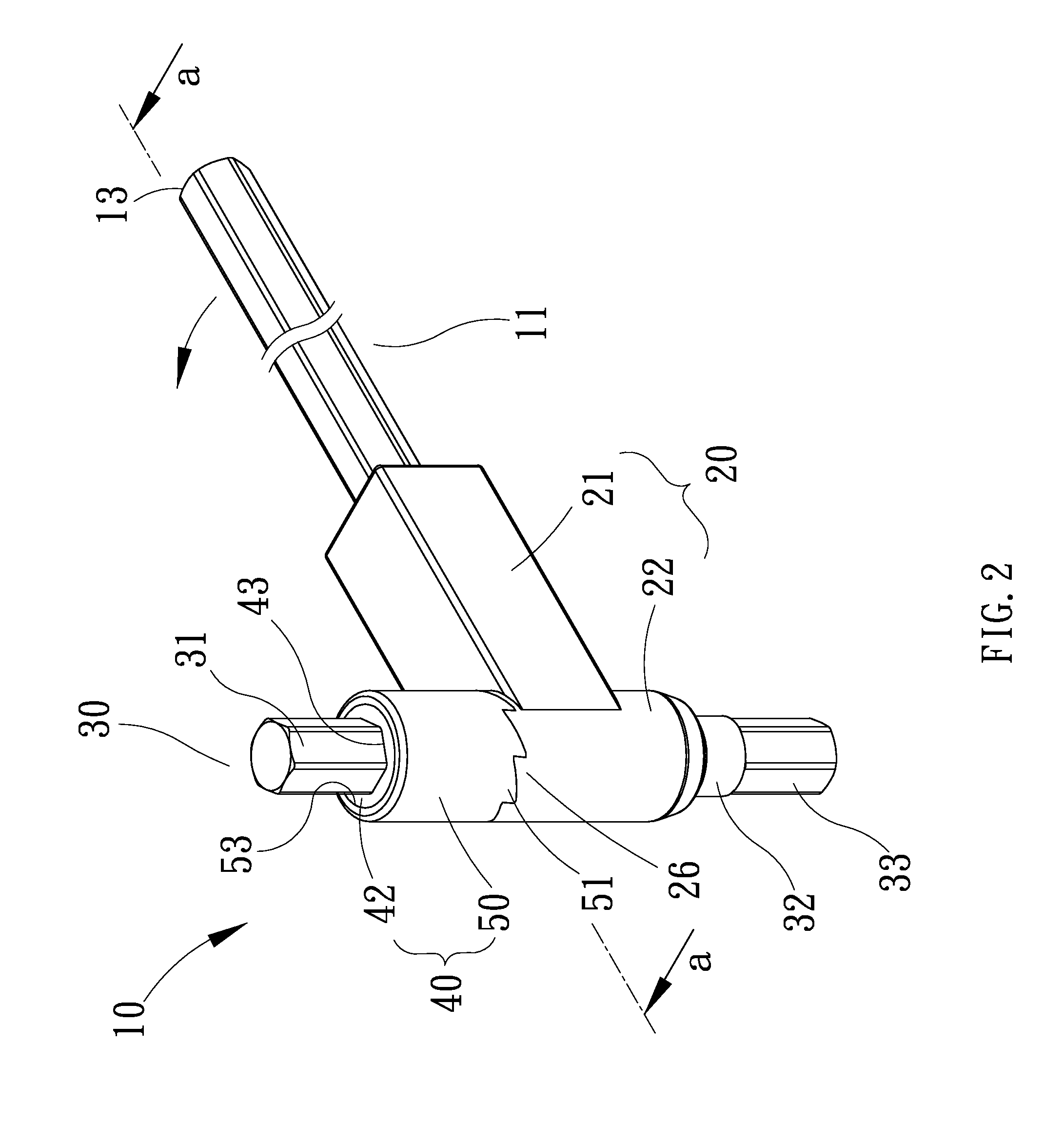
[0016]Referring to FIG. 1, a one-way driver 10 includes an extensive rod 11, a handle 20, a shaft 30 and an engagement unit 40 according to the preferred embodiment of the present invention. The extensive rod 11 is made with a hexagonal configuration in a cross-sectional view taken along a plane extending perpendicular to the axis thereof. The extensive rod 11 includes a first section 12 extending coaxially with a second section 13. Preferably, both of the sections 12 and 13 of the extensive rod 11 are made with a hexagonal configuration in a cross-sectional view taken along a plane extending perpendicular to the axis thereof. However, the second section 13 of the extensive rod 11 may be made with a circular configuration while the first section 12 of the extensive rod 11 is made with a hexagonal configuration. Alternatively, both of the sections 12 and 13 of the extensive rod 11 may be made with a circular configuration.

[0017]The handle 20 includes a socket 21 extending from a slee...


PUM


Abstract

A one-way driver includes a handle, a shaft and an engagement unit. The shaft is rotationally inserted through the handle. The engagement unit is used to engage the shaft with the handle when the handle is pivoted in a direction and allow disengagement of the shaft from the handle when the handle is pivoted in an opposite direction.

Description

BACKGROUND OF INVENTION[0001]1. Field of Invention[0002]The present invention relates to a hand tool and, more particularly, to a one-way driver.[0003]2. Related Prior Art[0004]Conventional one-way drivers can be found in Taiwanese Patents D131300 and D135897 for example. Such a conventional one-way driver includes a handle transversely provided on a rod. The rod is made of metal while the handle is made of plastics by injection molding. The rod includes a hexagonal configuration in a cross-sectional view taken along a plane extending perpendicular to the axis thereof. In use, a user uses a hand to insert the rod in a cavity defined in a screw. The user uses a hand to operate the handle to pivot the rod and hence the screw in a first direction for about ¾ round. Then, the user uses the hand to remove the rod from the cavity and pivot the rod in a second direction opposite to the first direction. Thus, the user returns the hand to the original position without returning the screw to ...

Claims


Application Information

Patent Timeline
Patent Type & Authority Patents(United States)
IPC IPC(8): B25B17/00
CPCB25B13/466B25B15/008
Inventor CHANG, HUI-LING
Owner CHANG HUI LING
Features
  • R&D
  • Intellectual Property
  • Life Sciences
  • Materials
  • Tech Scout
  • Unparalleled Data Quality
  • Higher Quality Content
  • 60% Fewer Hallucinations
Learn More