
Bicycle lighting systems and methods

a technology of bicycle lighting and bicycle lights, applied in the direction of identification means, instruments, anti-theft devices, etc., can solve the problems of bicycle light not providing adequate lighting or sighting, bicycle light not providing both sufficient lighting and sighting

Active Publication Date: 2012-12-25
WEISTECH TECH CO LTD
View PDF63 Cites 27 Cited by
  • Summary
  • Abstract
  • Description
  • Claims
  • Application Information

AI Technical Summary

Benefits of technology

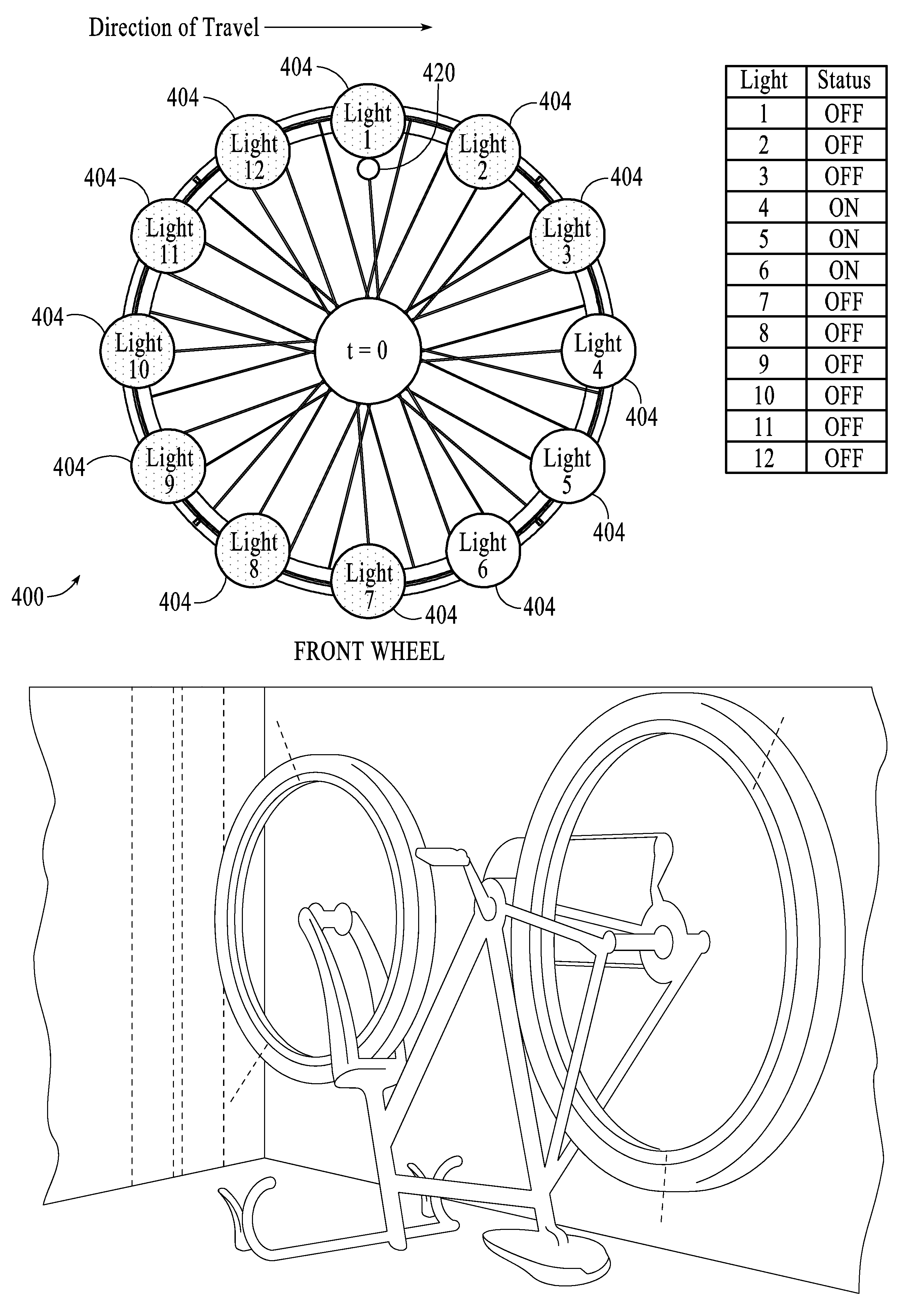
[0023]The lighting system may further include a controller mounted to the ring and coupled to the plurality of lights to control a state of each of the plurality of lights. The lighting system may further include an index sensor to sense a rotation of the wheel, and the controller may receive data from the index sensor and calculate a period of rotation or determine a reference position of the wheel. The index sensor may be a hall effect sensor coupled to the illumination ring and a magnet coupled to a fixed frame coupled to the wheel.

Problems solved by technology

Nearly 70% of all nighttime bicycle-car collisions are due to inadequate side visibility.
Currently, no bicycle light provides both sufficient lighting and sighting.
These lights, however, project light from the handlebars to a particular spot on the ground or directly in front of the rider and do not provide adequate lighting or sighting because they only project light in one direction and only illuminate a limited spot in front of the rider.
Furthermore, neither the handlebar lights or reflective back lights provide side lighting (i.e., inadequate sighting from the side of the bicycle).

Method used


Image

  • Bicycle lighting systems and methods
  • Bicycle lighting systems and methods
  • Bicycle lighting systems and methods

Examples


Embodiment Construction

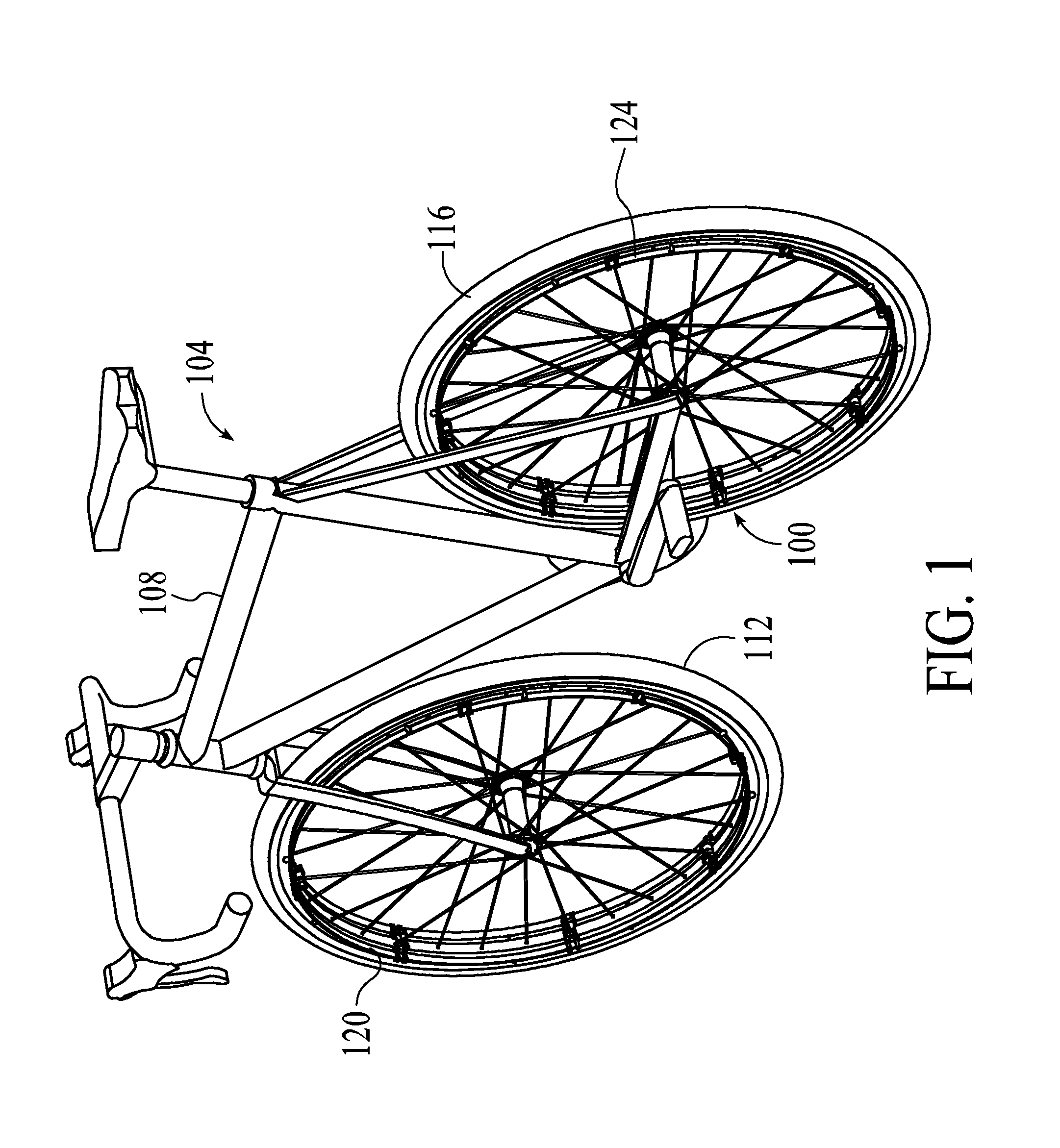
[0109]Embodiments of the invention are directed to a bicycle lighting system and method that provides both adequate lighting and sighting. Embodiments of the invention provide cyclists with superior lighting by fully illuminating the path in front of them. By moving the light source closer to the ground (i.e., by providing the light source one the wheels), embodiments of the invention enable cyclists to safely avoid potholes, debris, and other previously unseen dangers. The bicycle lighting system also functions to provide a swath of light in front of the bicycle, the light luminosity being of sufficient quantity (i.e. high enough) to illuminate the path in front of the rider. Furthermore, the bicycle lighting system provides a substantially visually continuous arc of light from the wheel. Unlike traditional bicycle lights, which project light in only one direction, embodiments of the invention cast 360 degrees of illumination (projecting light in front of the rider, to the back of ...


PUM


Abstract

Systems and methods for providing adequate lighting and sighting for a bicycle are disclosed. A lighting system that includes an illumination ring configured to be coupled to a wheel is also disclosed. The illumination ring is configured to simultaneously project light forward and to the side of a front wheel and to project light rearward of and to the side of a rear wheel. The illumination ring may be mounted to or integrated with the bicycle wheel. Methods of controlling light sources on the illumination ring are also disclosed.

Description

PRIORITY[0001]The present application claims priority to U.S. Provisional Application No. 61 / 508,184, filed Jul. 15, 2011, and entitled “Intelligent Bicycle Wheel Mounted Lighting System Capable of Forward Path Illumination While Maintaining 360 Degree Visibility,” and U.S. Provisional Application No. 61 / 559,055, filed Nov. 12, 2011, and entitled “Novel Clips for Attaching Illumination Ring to a Bicycle Wheel,” the entireties of which are hereby incorporated by reference.BACKGROUND[0002]1. Field[0003]This invention relates to bicycle lighting systems and methods and, more particularly, to an illumination ring couplable to a bicycle wheel, systems for coupling the illumination ring to the bicycle wheel and methods of providing illumination on a bicycle.[0004]2. Related Art[0005]The two most frequent causes for the 52,000 reported bicycle accidents in 2008 were collisions with motor vehicles (58%) and individual falls (30%). Of the 716 reported fatalities, 69% occurred in urban areas ...

Claims


Application Information

Patent Timeline
Patent Type & Authority Patents(United States)
IPC IPC(8): B62J6/00B60Q1/11
CPCB60Q1/326B62J6/001B62J6/00B62J6/01B62J6/20B62J6/057
Inventor FRANKOVICH, JOHN KENT
Owner WEISTECH TECH CO LTD
Learn More