Orthodontic appliance system

a technology for orthodontic appliances and braces, which is applied in the field of orthodontic appliance systems, can solve the problems of not being able to remove braces to eat and brush teeth, the braces themselves do not deliver force to the teeth, and the vast majority of them are not “comprehensive” in natur

Inactive Publication Date: 2013-01-22
MARSTON BLAKE E
View PDF19 Cites 60 Cited by
  • Summary
  • Abstract
  • Description
  • Claims
  • Application Information

AI Technical Summary

Benefits of technology

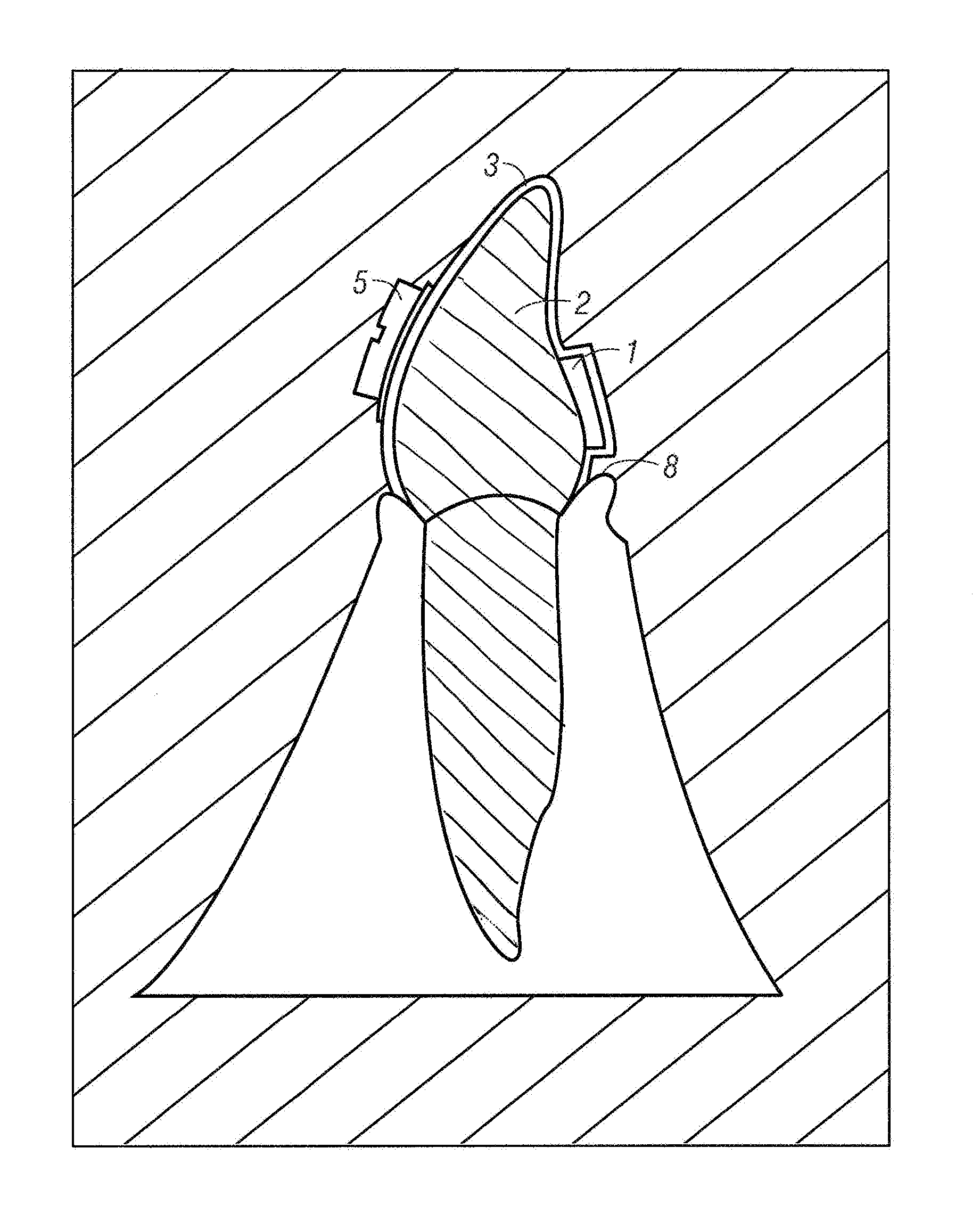
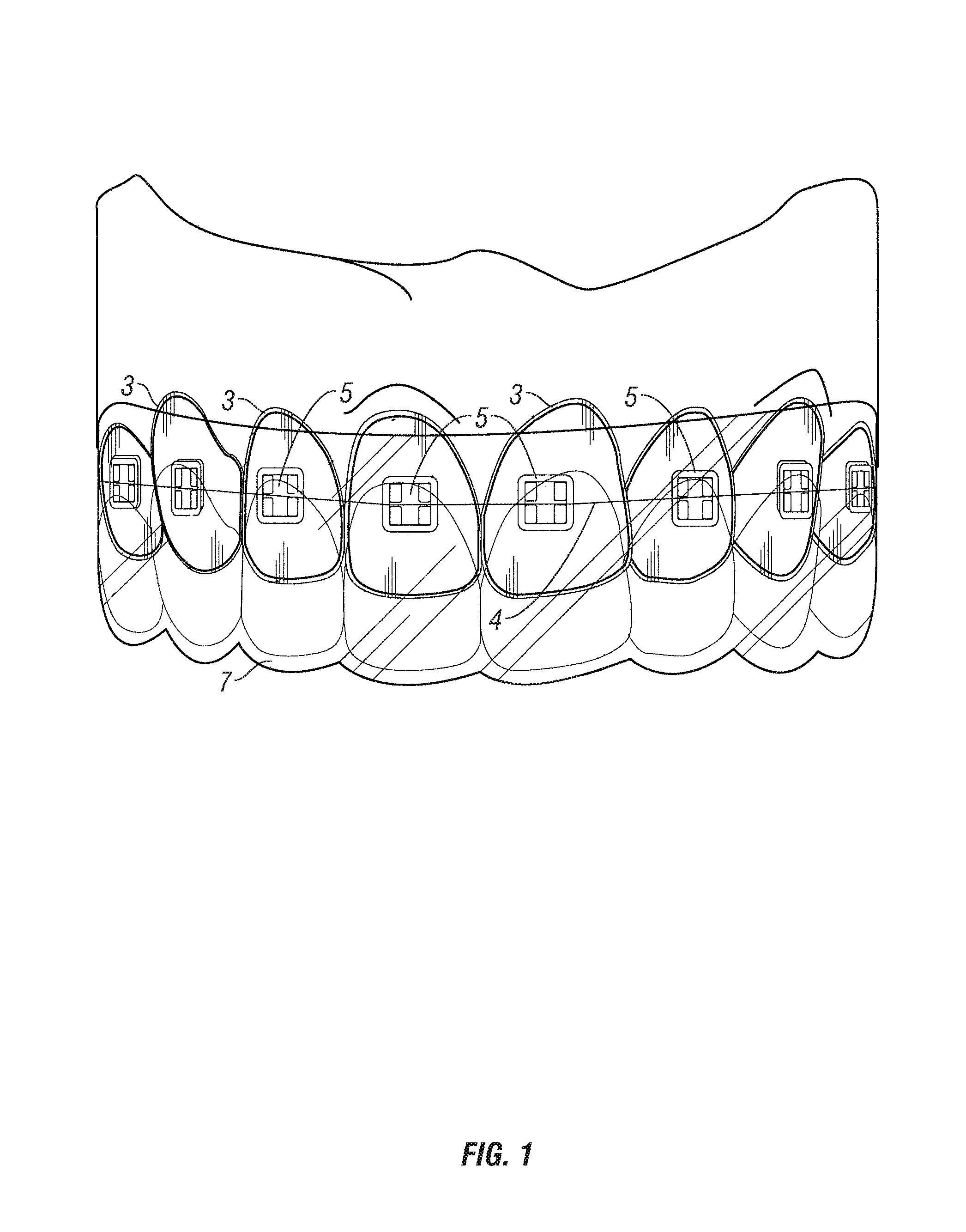
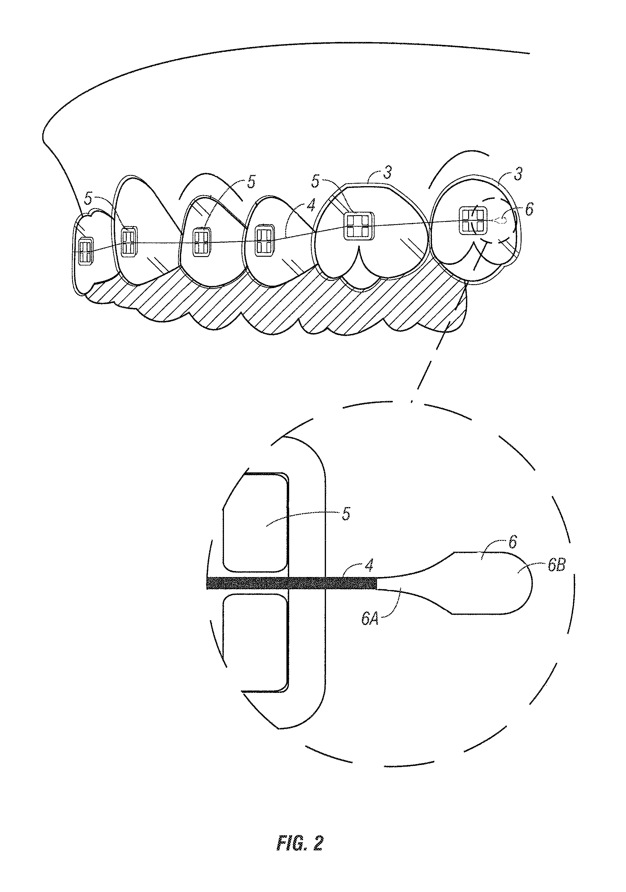
[0011]Broadly stated, the concept behind the device according to the invention is the creation of a type of “removable braces,” in which the brackets or other wire holder such as tubes and the wires as well are delivering the forces to the teeth without having to be glued or otherwise semi-permanently fixed to the teeth. Instead of being cemented to the teeth, the for example brackets and wires are attached to a clear aligner. The clear aligner is then sectioned along each individual tooth to create discrete plastic sleeves, each which fits over a respective tooth. The brackets are subsequently attached to the wire, making one continuous, interconnected appliance. In order to retain the plastic sleeve on a corresponding one of the teeth, a clip (for example comprised of metal or other suitable material) is glued for example to the backside of each tooth, not visible from the front. The clip allows the clear plastic sleeve to adhere firmly to the tooth by engagement thereof with the lingual surface-mounted clip. There is retention secure enough to maintain the plastic sleeve on the tooth, thereby delivering the forces from the braces to the teeth, but not too much force that the patient is unable to remove the appliance with his / her fingers.

Problems solved by technology

The brackets themselves do not deliver forces to the teeth.
A myriad of removable appliances have been developed over the years, but the vast majority of them are not “comprehensive” in nature.
For example, most patients dislike not being able to remove their braces to eat and brush their teeth.
The INVISALIGN system moves teeth much more slowly than braces, and is limited in its scope and potential.
The ESSIX device requires more training by the orthodontist, and is even more limited in its potential applications.

Method used


Image

  • Orthodontic appliance system
  • Orthodontic appliance system
  • Orthodontic appliance system

Examples


Embodiment Construction

[0019]The orthodontic appliance system according to an embodiment of the invention requires initial preparation and fitted installation for each patient on an individual basis. The method of fitting a patient with the system is described in the following.

[0020]To begin the process, a polyvinyl siloxane (PVS) impression of the dental arch to be treated is taken. It is also possible to obtain a model of a patient's mouth via an intraoral scanner. The file is then transmitted to a 3D or CAD CAM printer and a replica is created. The impression is subsequently poured in high-strength orthodontic stone, and separated from the impression once the stone is set. The FA point on the buccal surface of the teeth where the ideal bracket location will be is marked on the casting, for example, using a thin pencil to lightly mark surface. Lingual clips can be removably attached to the back (lingual) surfaces of the cast teeth using a temporary adhesive. An example of a suitable adhesive is THERMACU...


PUM


Abstract

A removable orthodontic appliance of discrete plastic sleeves, each being receivable over a corresponding tooth of a patient. Lingual clips are fastened to the corresponding tooth and which are engageable with corresponding structure of the sleeves for removably retaining each of said plastic sleeves to the corresponding tooth of the patient. Buccal brackets are fixably carried on a side of each of the sleeves positionally corresponding to a buccal surface of the corresponding tooth to which each of the sleeves is receivable. An arch wire is ligated to each of the buccal brackets to extend therebetween. The system can be conveniently removed for cleaning and adjustment.

Description

CROSS-REFERENCE TO RELATED APPLICATIONS[0001]This application claims priority under 35 U.S.C. §119 of a provisional application Ser. No. 61 / 270,247 filed Jul. 6, 2009, and which application is hereby incorporated by reference in its entirety.BACKGROUND OF THE INVENTION[0002]The invention relates to an orthodontic appliance system, and more particularly, to an orthodontic appliance system which allows temporary removal of the active orthodontic components from the teeth of a patient undergoing orthodontic realignment, for teeth brushing, eating, etc., and facilitated reinstallation by the patient without the aid of a dentist.[0003]For well over a century, orthodontists have been engaged in the process of repositioning teeth from a bad relationship, or “malocclusion,” into a healthier and more esthetic arrangement. In order to move teeth, three elements are generally required: 1) force, 2) time and 3) space. The mouth responds to a sustained force placed on a tooth by rearranging, or ...

Claims


Application Information

Patent Timeline
Patent Type & Authority Patents(United States)
IPC IPC(8): A61C7/00
CPCA61C7/08A61C7/14A61C7/145A61C7/20B33Y80/00
Inventor MARSTON, BLAKE E.
Owner MARSTON BLAKE E
Why Eureka
Try Eureka