
Motorcycle suspension method and sway dampening apparatus

a technology for dampening apparatus and motorcycles, which is applied in the field of motorcycle suspension methods and sway dampening apparatus, can solve the problems of rider losing control of the motorcycle, prone to problems, and generally more dangerous motorcycles than automobiles, and achieve the effects of eliminating “wobble”, durable and hard materials, and the same durability and dampening capability

Inactive Publication Date: 2013-03-05
ORE JEREMY
View PDF6 Cites 0 Cited by
  • Summary
  • Abstract
  • Description
  • Claims
  • Application Information

AI Technical Summary

Benefits of technology

The solution significantly improves motorcycle handling by eliminating 'wallow' and 'tank slapper' issues, enhancing stability and ride quality, while maintaining the natural movement of engine and transmission components.

Problems solved by technology

However, statistics show that motorcycles are generally more dangerous than automobiles.
Specifically, the front wheel can thrash from side to side, something motorcycle riders refer to as a “tank slapper” because the handlebars suddenly seem intent on battering the fuel tank into submission, causing the rider to lose control of the motorcycle.
Certain Harley-Davidson motorcycle models appear to be more prone to the problem than others.
The “FLH” series of Harley-Davidson motorcycles, also frown as the Electra Glide, Road King and Ultra Classic, which are widely used by law enforcement officers nationwide have been documented as being prone to instability.
Because the parent invention does not stand on its own, but rather builds upon the existing OEM rubber mount, the Parent Invention has not been one hundred percent successful.

Method used


Image

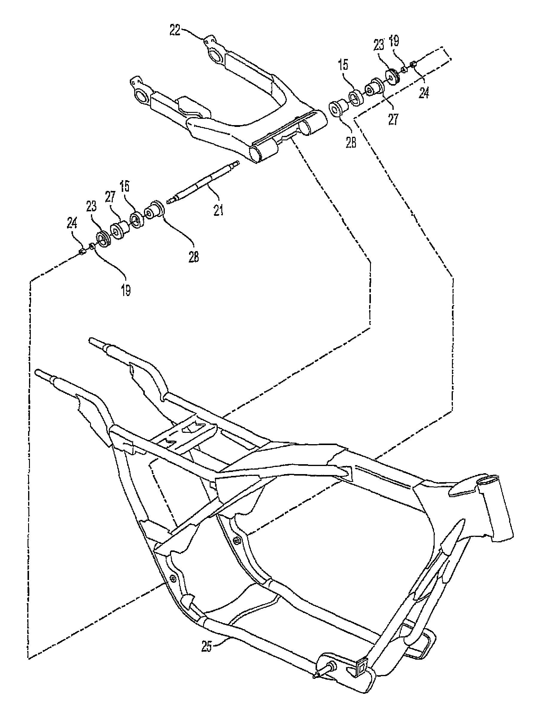
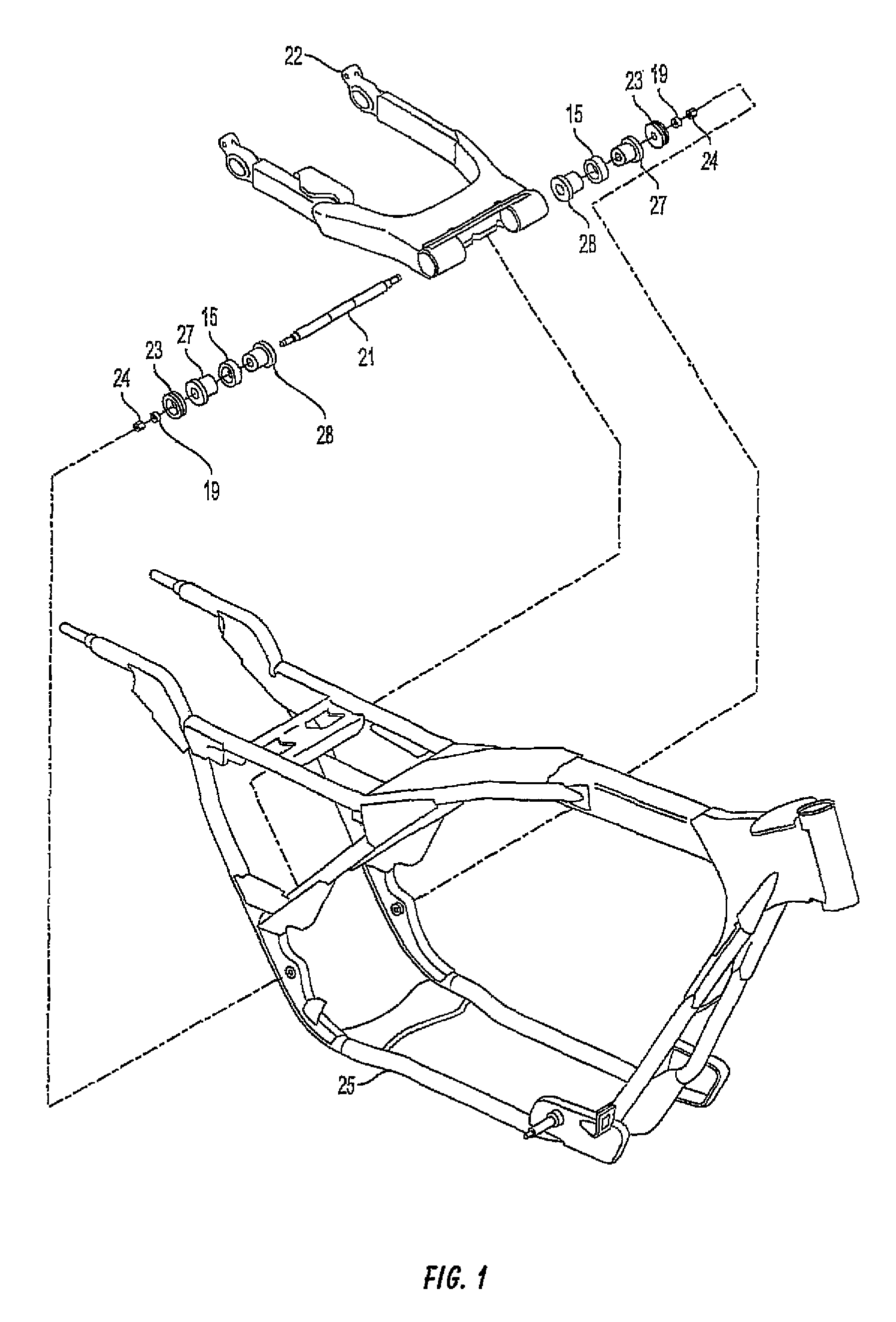
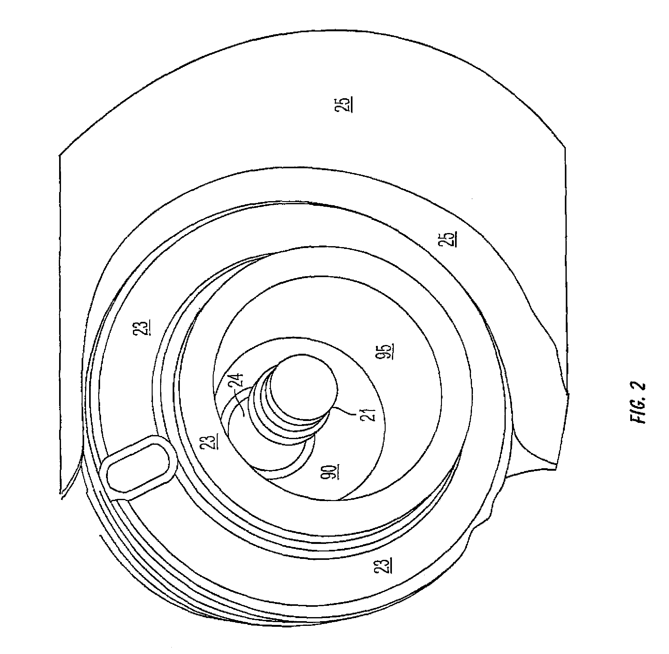
  • Motorcycle suspension method and sway dampening apparatus
  • Motorcycle suspension method and sway dampening apparatus
  • Motorcycle suspension method and sway dampening apparatus

Examples


Embodiment Construction

[0024]The following description is provided to enable any person skilled in the art to make and use the invention and sets forth the best modes contemplated by the inventor of carrying out his invention. Various modifications, however, will remain readily apparent to those skilled in the art, since the generic principles of the present invention have been defined herein specifically to provide a Motorcycle Suspension Method and Sway Dampening Apparatus.

[0025]In the following paragraphs, a stability suspension system (“SSS”) kit, apparatus and method will be described in detail by way of example with reference to the attached drawings. While the SSS is capable of embodiment in many different forms, there is shown in the drawings and will herein be described in detail specific embodiments, with the understanding that the present disclosure is to be considered as an example of the principles of the SSS and not intended to limit the SSS to the specific embodiments shown and described. T...


PUM

PropertyMeasurementUnit
lengthsaaaaaaaaaa
lengthsaaaaaaaaaa
inner diameteraaaaaaaaaa

Abstract

A Motorcycle Suspension Method and Sway Dampening Apparatus. Rather than selectively replacing portions of the prior motorcycle dampening apparatus, the apparatus and method of the present invention replaces the conventional dampening bushing within the OEM pivot shaft assembly. The replacement combination motor mount and bushing provides at least the same durability and dampening capability the OEM device, while eliminating the “wobble” experienced by virtually all OEM motorcycles having the prior rear pivot mount design. The replacement mount and bushing element comprises at least two different plasticized materials combined into a single element. The combination mount and bushing is made partially from a softer, pliable dampening material, as well as a more durable and hard material. Installation of the combination mount and bushing element eliminates the need for an asymmetric pivot shaft orientation, since the central bore of this element is centered on the geometric axis of the element.

Description

[0001]This application is a continuation-in-part of application Ser. No. 12 / 154,456, filed May 22, 2008, (the “Parent Application”), now U.S. Pat. No. 7,967,097.BACKGROUND OF THE INVENTION[0002]1. Field of the Invention[0003]This invention relates generally to motorcycles and, more specifically, to a Motorcycle Suspension Method and Sway Dampening Apparatus.[0004]2. Description of Related Art[0005]The popularity of motorcycling continues to increase. Riders are attracted to the freedom of the open road, leaving behind the cares and worries of everyday life. Motorcycle manufacturers have seized upon the recent surge in popularity and have been selling motorcycles and accessories in record numbers.[0006]However, statistics show that motorcycles are generally more dangerous than automobiles. For example, certain Harley-Davidson motorcycle models exhibit what is commonly referred to as a “high-speed wobble” (or “tank-slapper”) which typically involves shaking or instability. Specificall...

Claims


Application Information

Patent Timeline
Patent Type & Authority Patents(United States)
IPC IPC(8): B62K25/04
CPCB62K25/283Y10T29/49826
Inventor ORE, JEREMY
Owner ORE JEREMY
Learn More