
Stackable chair with flexible back

a flexible back and seat technology, applied in the field of seat seats, can solve the problems of less comfortable chairs, complicated mechanisms, and high manufacturing costs

Active Publication Date: 2013-03-05
MITY-LITE
View PDF108 Cites 28 Cited by
  • Summary
  • Abstract
  • Description
  • Claims
  • Application Information

AI Technical Summary

Problems solved by technology

However, such efforts have often led to complicated mechanisms that would be expensive to manufacture, or less comfortable chairs, for example chairs in which only part of the back support flexes.

Method used


Image

  • Stackable chair with flexible back
  • Stackable chair with flexible back
  • Stackable chair with flexible back

Examples


Embodiment Construction

[0014]The following detailed description is of the best currently contemplated modes of carrying out exemplary embodiments of the invention. The description is not to be taken in a limiting sense, but is made merely for the purpose of illustrating the general principles of the invention, since the scope of the invention is best defined by the appended claims.

[0015]Various inventive features are described below that can each be used independently of one another or in combination with other features.

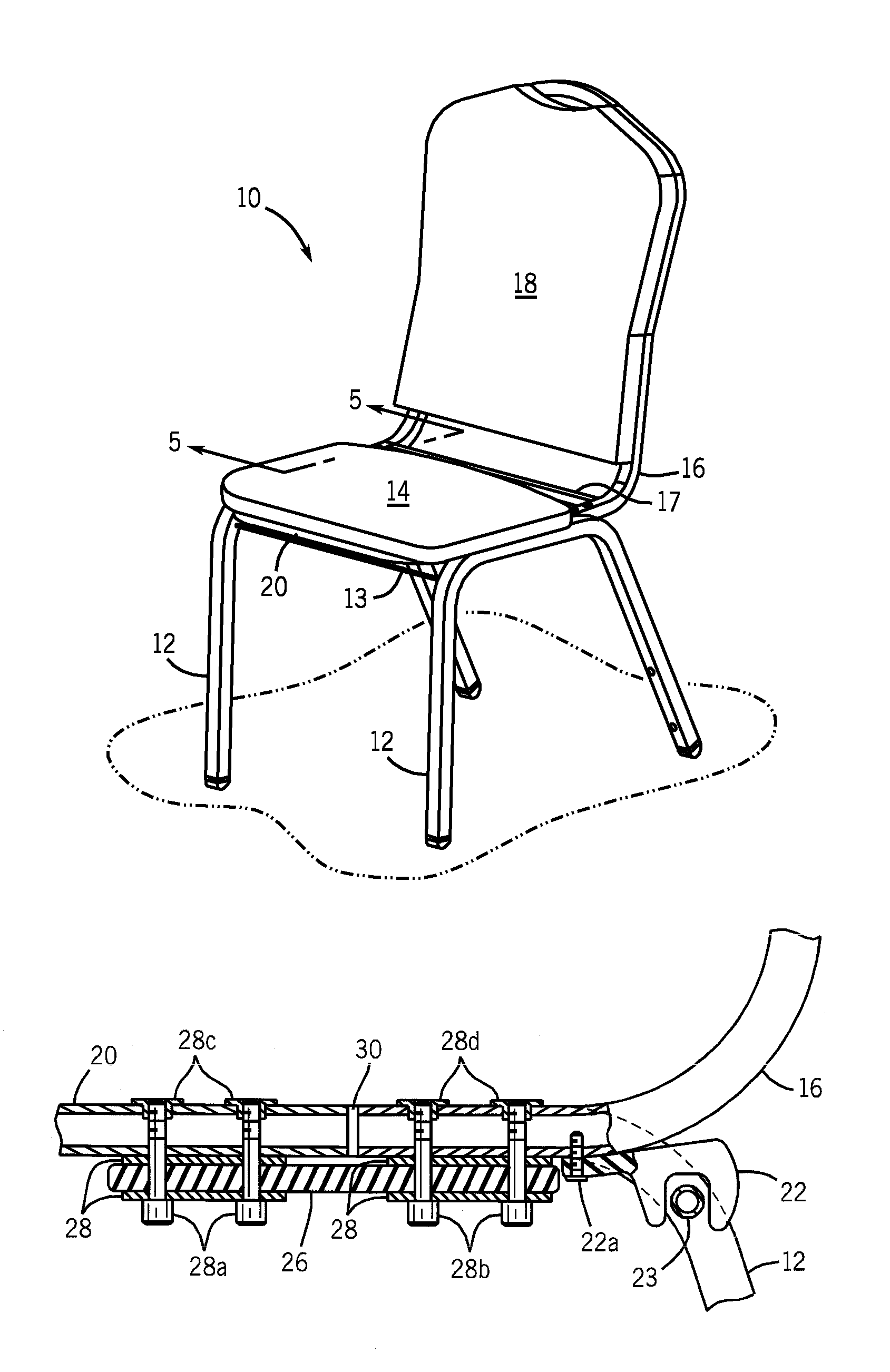
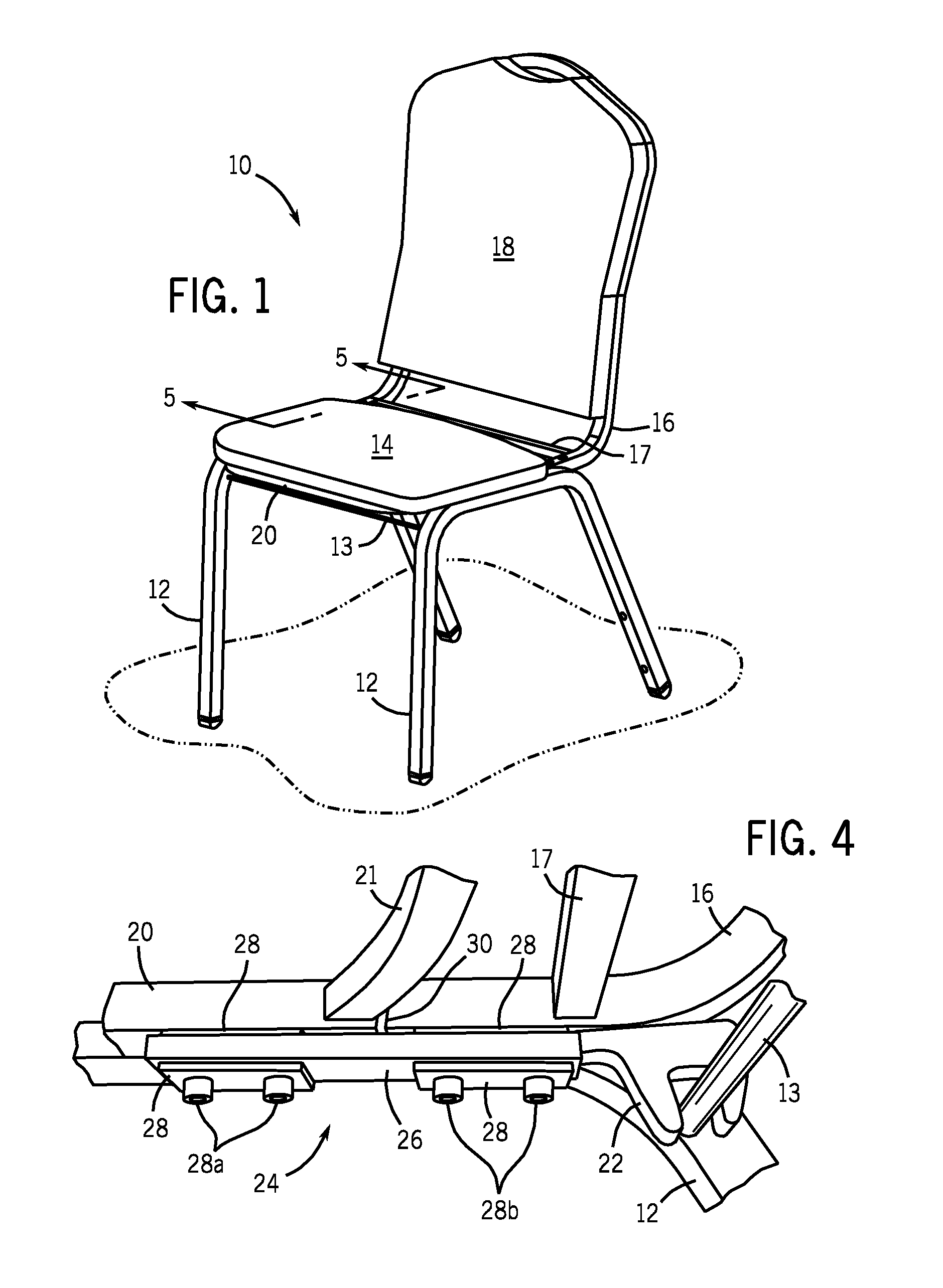
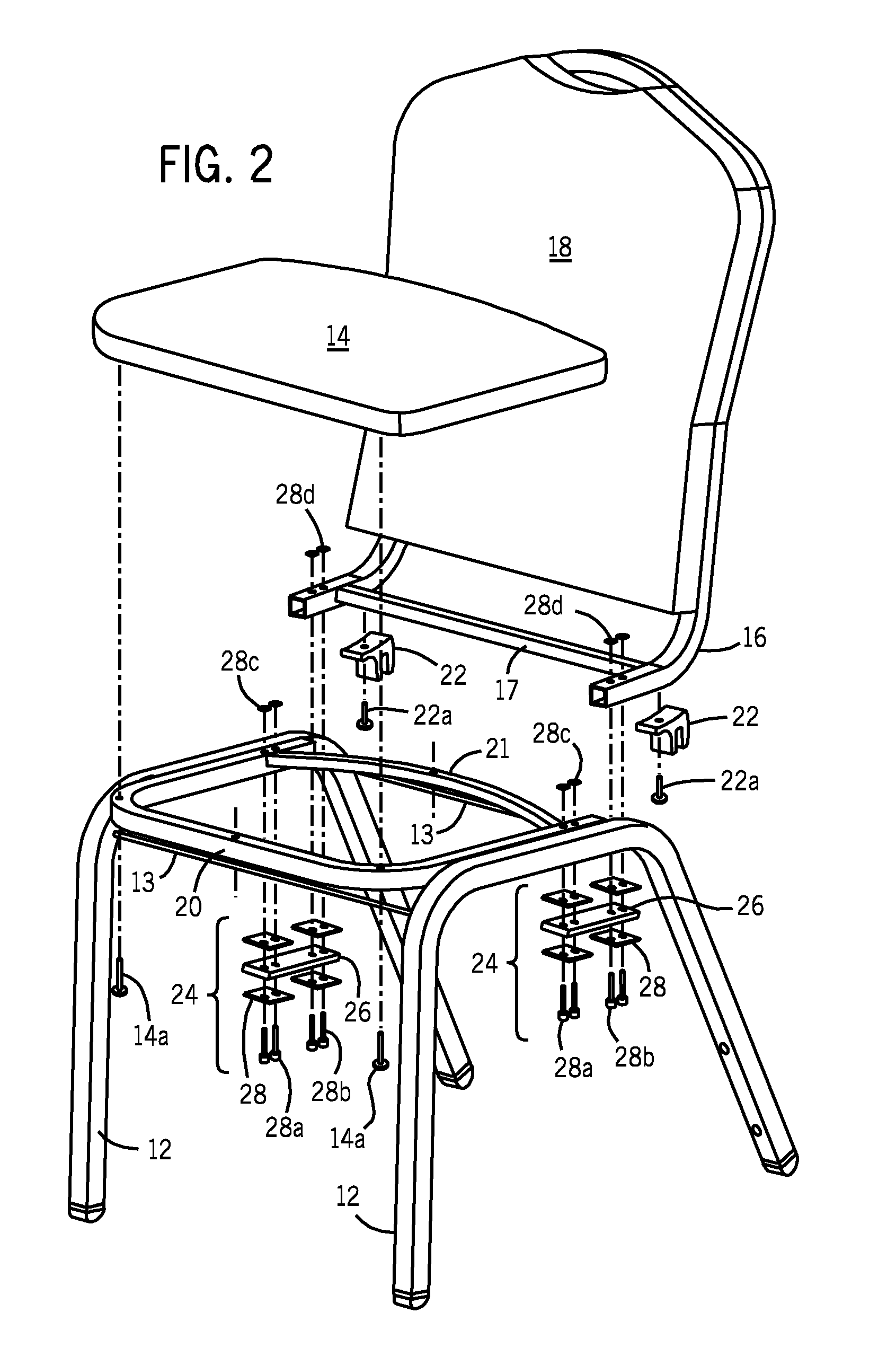
[0016]Broadly, an embodiment of the present invention provides a stackable chair having a back member that may flex to allow for improved user comfort. Embodiments of the present invention may include an inline spring-to-frame configuration with a pair of spring members reinforced by non-welded steel plates independent of the frame on the top and bottom of each end of each spring attached to the underside of the left and right members of the seat support frame. The spring-to-frame configur...


PUM


Abstract

A stackable chair having a back member may flex to allow for improved user comfort. An inline spring-to-frame configuration with a pair of spring members reinforced by steel plates on the top and bottom of each end of each spring is attached to the underside of the left and right members of the seat support frame. The spring-to-frame configuration may allow the back support frame to flex relative to the seat support frame.

Description

BACKGROUND OF THE INVENTION[0001]The present invention relates to stackable chairs and, more particularly, to stackable chairs having a back portion that may flex to improve the comfort of the occupant.[0002]Chairs for extended seating applications, such as banquet halls and conference rooms, are preferably comfortable, durable, and either stackable or nestable for storage purposes. Traditional stackable banquet chairs include a pair of inverted-U-shaped leg members attached to opposite sides of a generally horizontal seat. A generally L-shaped back support frame interconnects with the leg members and extends upwardly from the rear of the seat to support a back cushion. This type of chair may be stacked by placing the inverted-U-shaped leg members of one chair over the top of the leg members of another chair, such that the seat of the upper chair is supported just above the seat of the lower chair.[0003]Numerous attempts have been made to improve the comfort level of chair occupants...

Claims


Application Information

Patent Timeline
Patent Type & Authority Patents(United States)
IPC IPC(8): A47C3/00
CPCA47C7/445
Inventor BERTOLINI, JAMESPROCK, BRUCE WILLIAM
Owner MITY-LITE
Learn More