Process for manufacturing a single-piece blisk with a temporary blade support ring removed after a milling finishing step

a manufacturing process and blade support technology, applied in manufacturing tools, machines/engines, forging/pressing/hammering apparatus, etc., can solve the problems of limiting production costs and production times, and achieve the effects of limiting or eliminating deformation and vibration of blades, high advance rates, and reducing production costs

Active Publication Date: 2013-04-30
SN DETUDE & DE CONSTR DE MOTEURS DAVIATION S N E C M A
View PDF22 Cites 0 Cited by
  • Summary
  • Abstract
  • Description
  • Claims
  • Application Information

AI Technical Summary

Benefits of technology

[0011]The invention is thus remarkable in that during the cutting step using an abrasive water jet, it creates connecting means between at least two blade preforms, and preferably between all these blade preforms. This can strongly limit or even eradicate deformations and vibrations of blades while they are being manufactured, since they remain fixed to each other mechanically by material in the initial block.
[0012]This specific feature means that the different tools can be used at high advance rates thus reducing production times, without jeopardising the quality of the finished blisk. Furthermore, the reduction of production times and the reduction of blade vibrations during manufacturing slow tool wear, and particularly wear of milling machines, which advantageously limits production costs.
[0024]Preferably, the diameter of said single-piece blisk is greater than or equal to 800 mm. In this respect, note that the presence of connecting means holding the blades together during manufacturing makes it possible to manufacture large diameter blisks with long blades since the blade deformations and vibrations are reduced or even eliminated. Preferably, the minimum length of the blades is 150 mm.

Problems solved by technology

Furthermore, the reduction of production times and the reduction of blade vibrations during manufacturing slow tool wear, and particularly wear of milling machines, which advantageously limits production costs.

Method used


Image

  • Process for manufacturing a single-piece blisk with a temporary blade support ring removed after a milling finishing step
  • Process for manufacturing a single-piece blisk with a temporary blade support ring removed after a milling finishing step
  • Process for manufacturing a single-piece blisk with a temporary blade support ring removed after a milling finishing step

Examples


Embodiment Construction

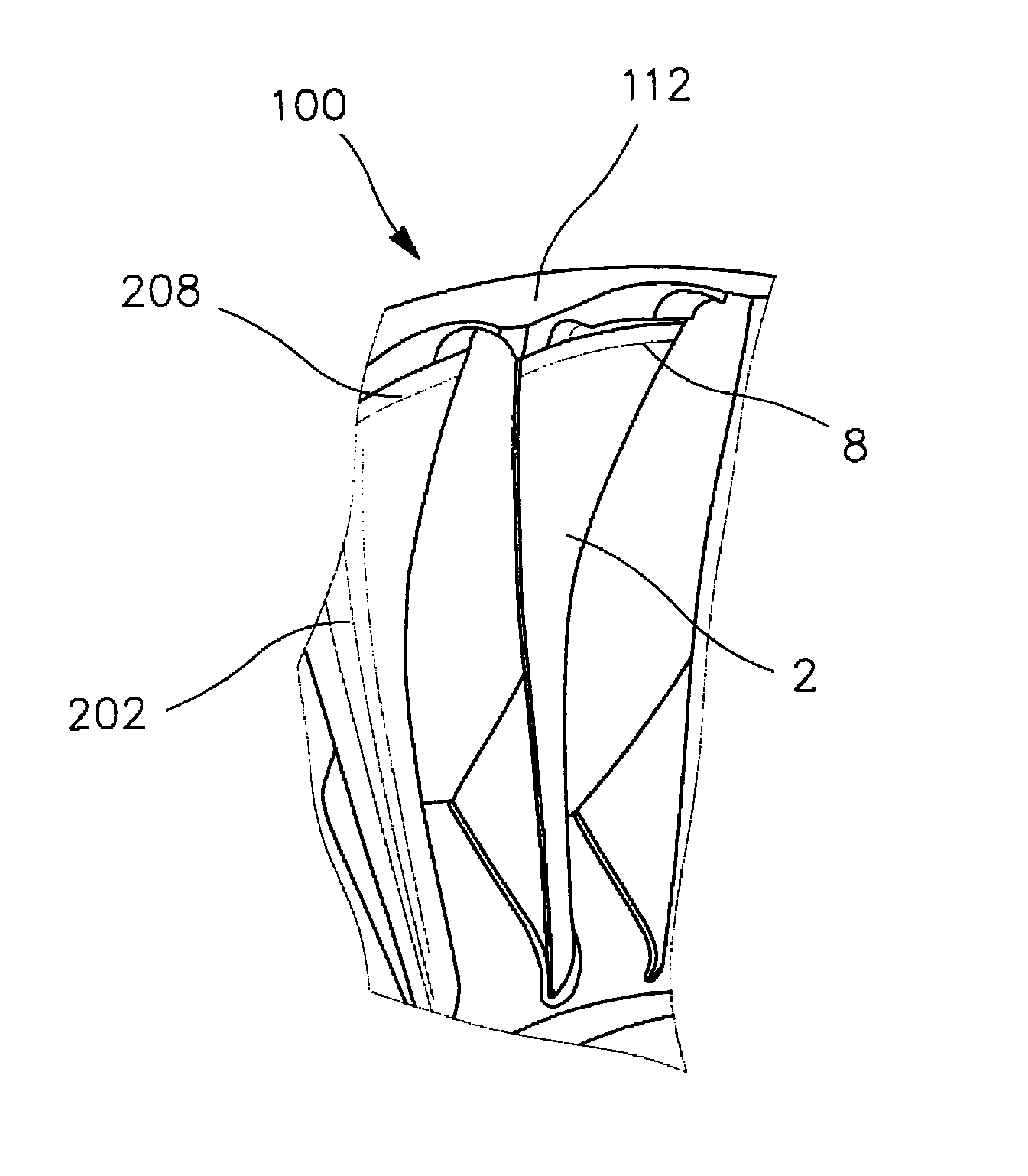
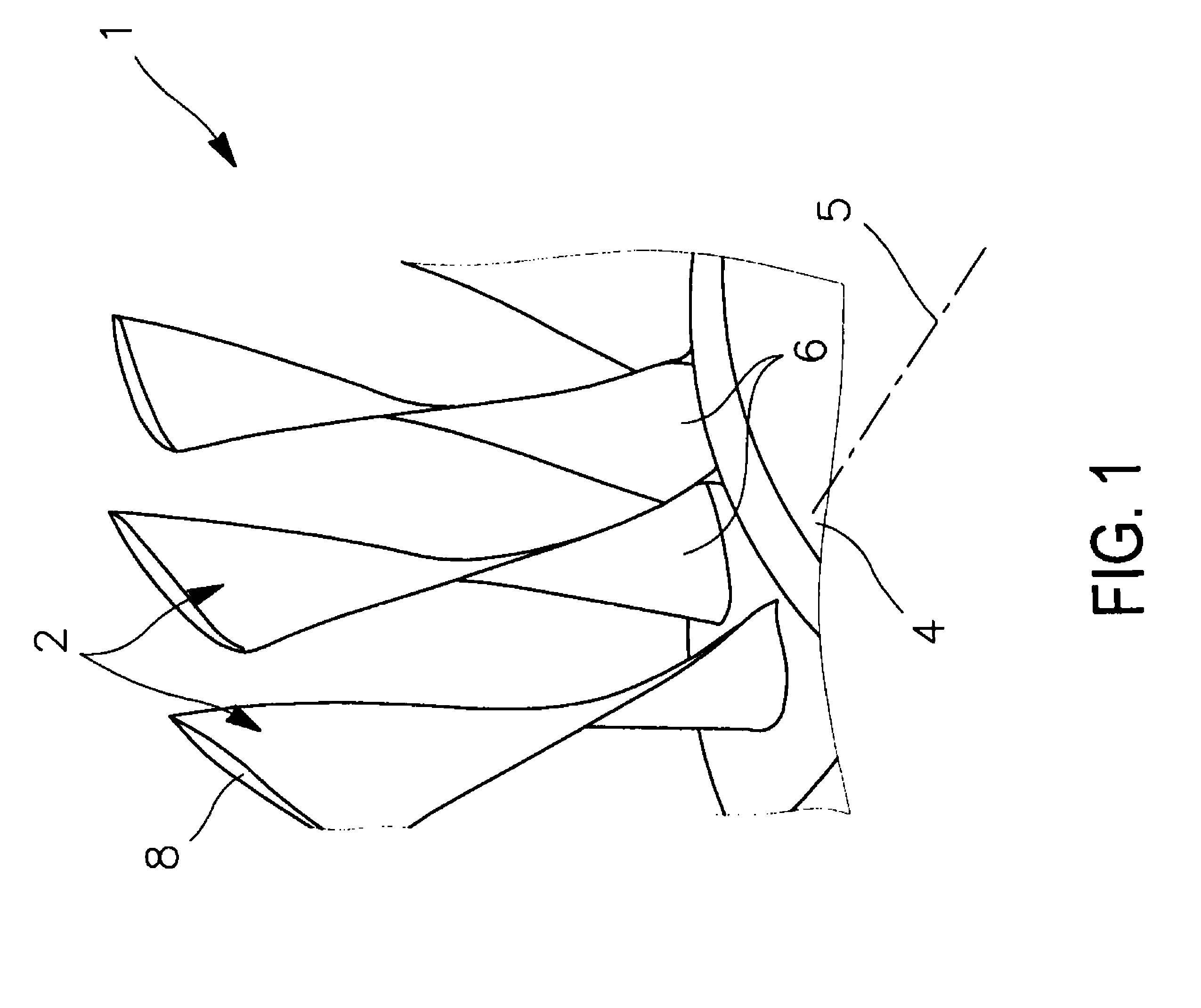
[0034]Firstly with reference to FIG. 1, the figure shows a single-piece blisk 1 to be obtained by the use of a manufacturing process according to this invention. It is preferably intended to form part of a compressor or turbine rotor for an aircraft turbine engine.

[0035]The single-piece blisk, hereinafter referred to as a blisk that is to be obtained using the process according to this invention is large, in other words its diameter is greater than or equal to 800 mm, the lengths of its blades 2 are not less than 150 mm and the thickness > of its disk 4 is greater than or equal to 130 mm. Furthermore, the blades supported by the disk 4 with its central axis 5 are strongly twisted with an angle of twist up to or even more than 45°. For information, this angle is equal to the fictitious angle between the root 6 and the tip 8 of a specific blade 2, according to conventional practice.

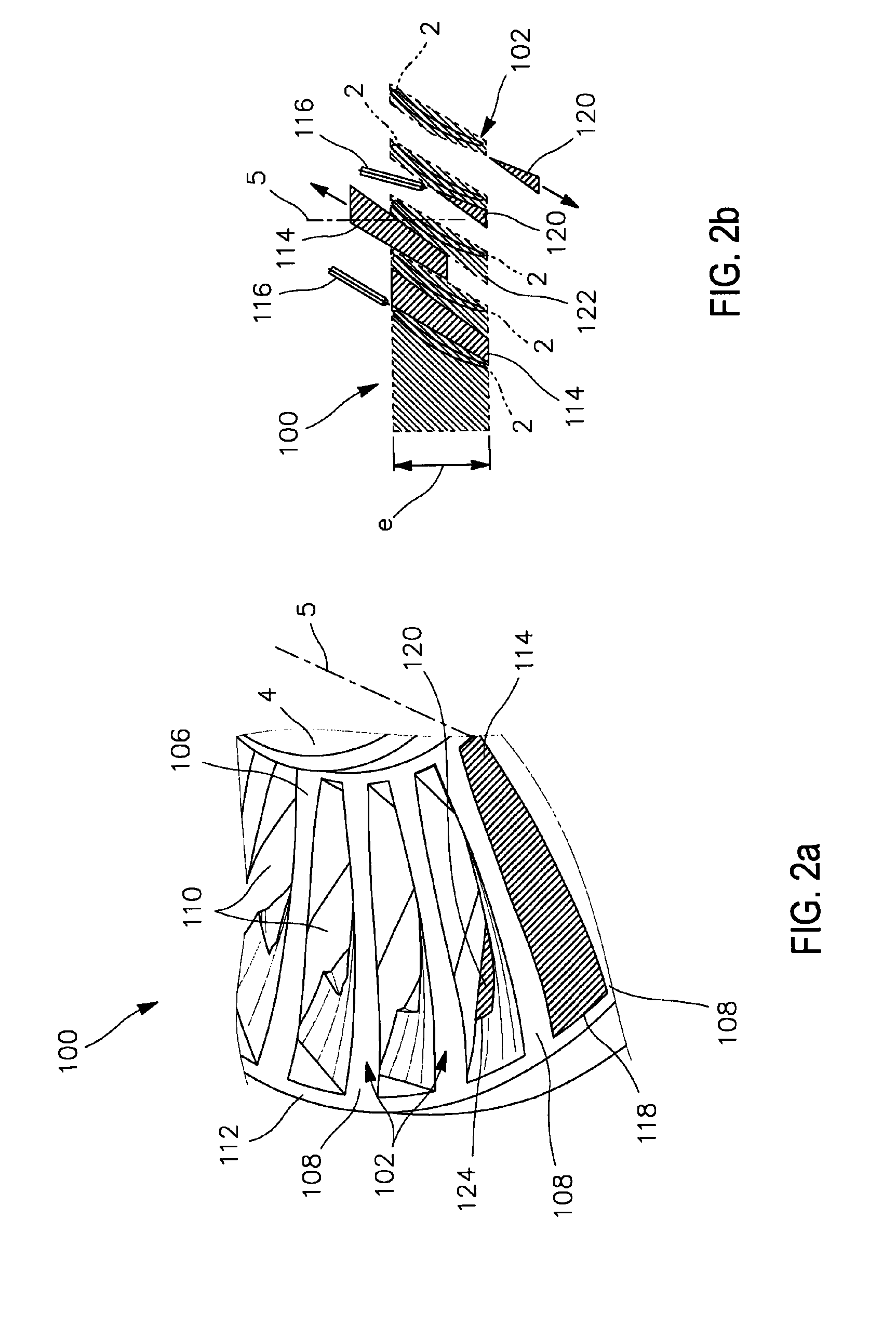
[0036]A preferred embodiment of the process for manufacturing the blisk 1 will now be described with ref...


PUM

PropertyMeasurementUnit
diameteraaaaaaaaaa
thicknessaaaaaaaaaa
lengthaaaaaaaaaa

Abstract

A process for manufacturing a single-piece blisk, including: using an abrasive water jet to cut a block of material, so as to create blade preforms extending radially outwards from a disk, while keeping material forming a connecting mechanism between at least two directly consecutive blade preforms; then milling on the blade preforms so as to obtain profiled blade blanks; then a finishing by milling of the blade blanks, so as to obtain blades with a final profile; then removing the connecting mechanism.

Description

TECHNICAL DOMAIN[0001]This invention relates in general to the manufacturing of single-piece blisks, preferably for an aircraft turbine engine.STATE OF PRIOR ART[0002]A single-piece bladed disk, also called a blisk, can be made using an abrasive water jet to cut a material block followed by one or more milling steps.[0003]The use of a cutting step using an abrasive water jet prior to milling can considerably reduce the manufacturing times and costs in comparison with a process based solely on milling. This is particularly due to the fact that such a manufacturing process requires removal of about 75% of the material in the original block to make the blisk. The removal of a large part of this material by cutting with an abrasive jet can reduce production times and also limits wear of milling machines.[0004]Nevertheless, this process cannot be considered to be fully optimised. The presence of deformations and vibrations of the blades during this process is a disadvantage, that becomes...

Claims


Application Information

Patent Timeline
Patent Type & Authority Patents(United States)
IPC IPC(8): B21D53/78B24C5/02B24B1/00
CPCB23C3/18B23P13/02B23P15/006B24C1/045F01D5/34B24C1/086B23C2220/28B23C2220/60Y10T29/49316F05D2230/10Y10T29/4932Y10T29/49325Y10T29/49336
Inventor BERLANGER, SERGEBORDU, SEBASTIENMALEVILLE, THIERRY JEANROCA, CHRISTOPHE CHARLES MAURICE
Owner SN DETUDE & DE CONSTR DE MOTEURS DAVIATION S N E C M A
Why Eureka
Try Eureka