
Casement window lock

a casement window and lock technology, applied in the field of casement windows, can solve the problems of prior casement window locks not having a sufficient movement range, prior casement window locks often not having sufficient locking force,

Active Publication Date: 2013-05-28
ASHLAND HARDWARE LLC
View PDF107 Cites 17 Cited by
  • Summary
  • Abstract
  • Description
  • Claims
  • Application Information

AI Technical Summary

Benefits of technology

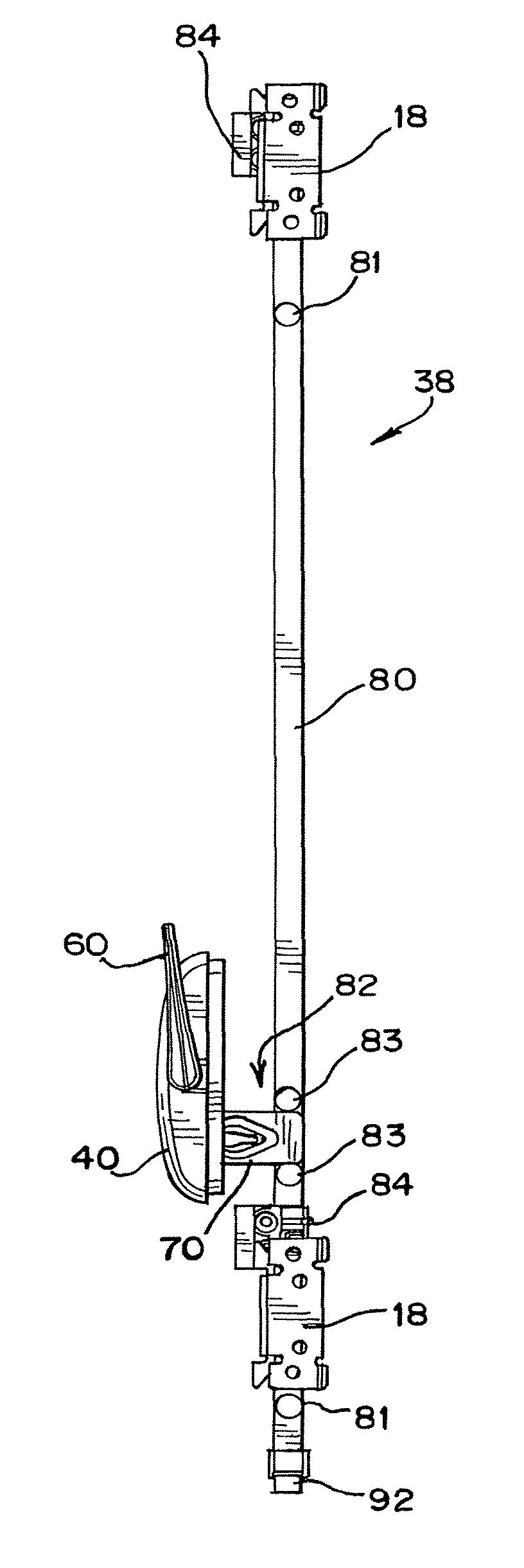
The present invention provides a locking mechanism for a casement window assembly. The mechanism includes a housing, an actuator, and a linkage member. The actuator is connected to the housing and can pivot about a fulcrum. The linkage member has two channels and receives the actuator's pins in these channels. Pivoting the actuator causes the linkage member to move along the window assembly's opening, from one position to another. The linkage member has inner surfaces that are engaged by the actuator's pins, allowing for force exerted on the inner surfaces to move the linkage member. The linkage member travels along a path from one position to another, with the actuator's pins exerting force on the inner surfaces of the channels. The invention also provides a lock assembly, a lock bar, and a retainer for the casement window assembly. The locking mechanism can be easily operated to lock or unlock the window assembly.

Problems solved by technology

However, prior casement window locks often do not generate sufficient locking force as desired by a user.
Additionally, prior casement window locks often do not have a sufficient range of movement.
Prior casement window locks also suffer from other disadvantages.

Method used


Image

  • Casement window lock
  • Casement window lock
  • Casement window lock

Examples


Embodiment Construction

[0051]While this invention is susceptible of embodiments in many different forms, there are shown in the drawings and will herein be described in detail preferred embodiments of the invention with the understanding that the present disclosure is to be considered as an exemplification of the principles of the invention and is not intended to limit the broad aspect of the invention to the embodiments illustrated.

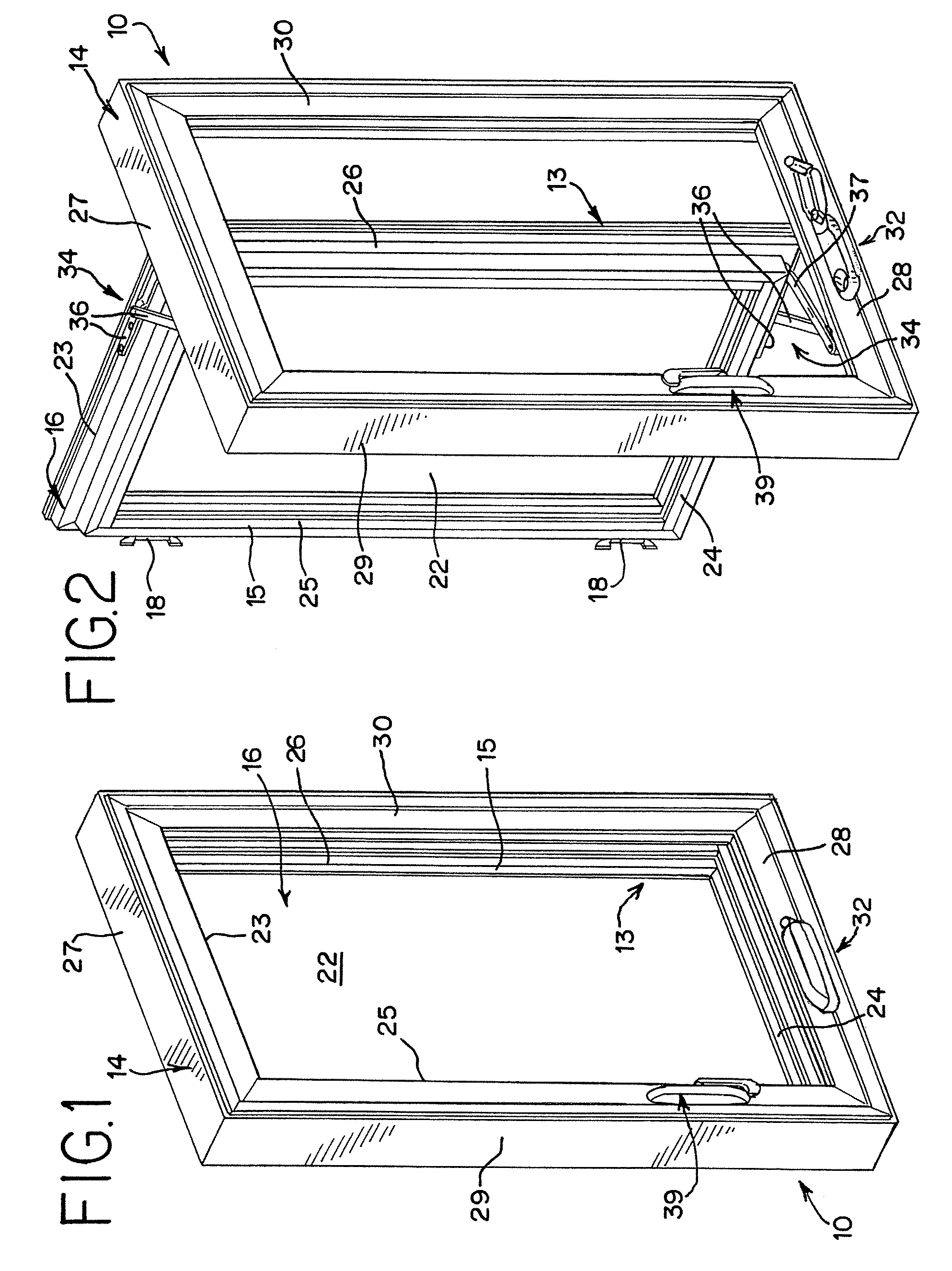
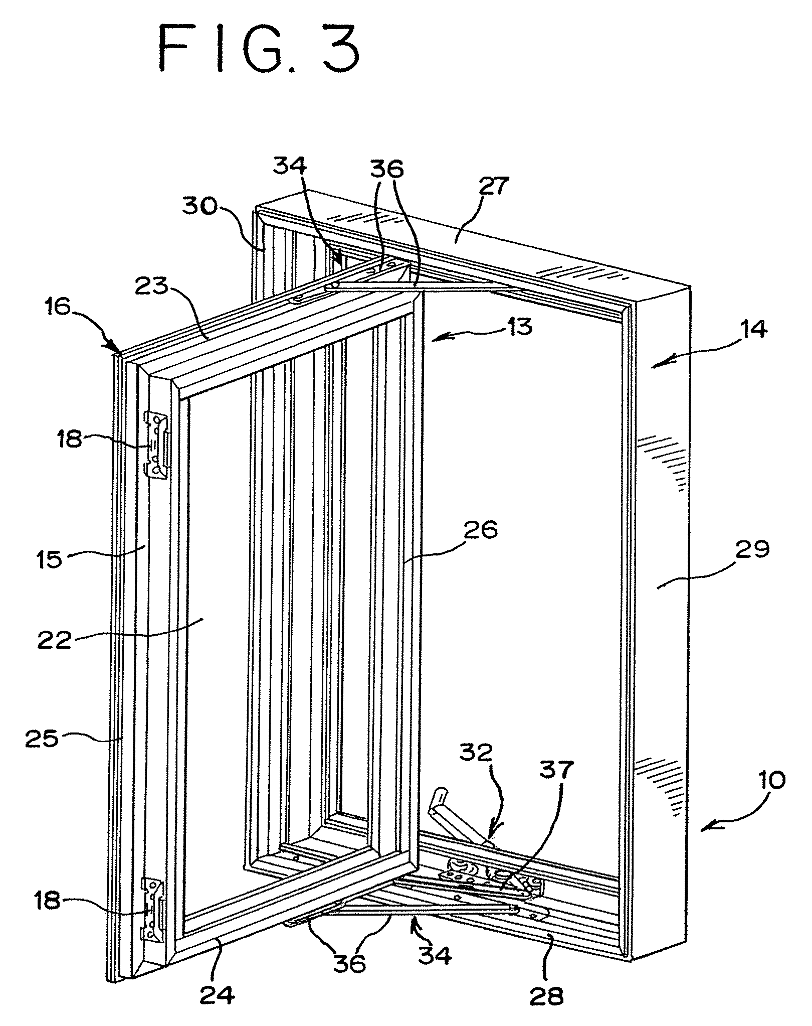
[0052]FIG. 1 shows a casement window assembly 10, which includes a jamb frame assembly or window frame 14, and an inner window assembly or window 16. The window 16 is formed of a sash frame 15 bordering a window pane 22. The sash frame 15 is formed by two vertical rails 25,26 and two horizontal rails 23,24. The window frame 14 is formed by two vertical jambs 29,30 and two horizontal jambs 27,28. The window 16 and window frame 14 are secured by hinged connection 13, such that the window 16 is moveable between an open and closed configuration relative the frame 14 by pivotal mov...


PUM


Abstract

A locking mechanism for a casement window assembly includes a housing adapted to be mounted on the window assembly, an actuator operably connected to the housing and pivotable about a fulcrum, and a linkage member having a first channel and a second channel. The housing has an elongated opening having opposed ends. The actuator includes an actuator body having a first pin and a second pin located thereon. The linkage member is connected to the actuator such that the first pin is received in the first channel and the second pin is received in the second channel. Pivoting the actuator about the fulcrum causes the first pin to move within the first channel and the second pin to move within the second channel, moving the linkage member along the opening, from one end of the opening to the other end of the opening.

Description

CROSS-REFERENCE TO RELATED APPLICATIONS[0001]The present application is a continuation-in-part of and claims the benefit of U.S. Provisional Patent Application No. 60 / 814,020, which application is incorporated by reference herein and made a part hereof.FEDERALLY SPONSORED RESEARCH OR DEVELOPMENT[0002]None.TECHNICAL FIELD[0003]The invention relates to casement windows, and more specifically, to a locking mechanism for locking and unlocking a casement window having increased mechanical advantage and greater range of movement in locking.BACKGROUND OF THE INVENTION[0004]Casement windows and locking mechanisms therefor are known in the art. However, prior casement window locks often do not generate sufficient locking force as desired by a user. Additionally, prior casement window locks often do not have a sufficient range of movement. Prior casement window locks also suffer from other disadvantages.[0005]The present invention is provided to solve the problems discussed above and other pr...

Claims


Application Information

Patent Timeline
Patent Type & Authority Patents(United States)
IPC IPC(8): E05C9/10
CPCE05B7/00E05C9/02E05C9/22E05B15/0053E05C9/1858Y10T292/0844Y10T292/0915Y10T292/1014Y10T292/1039
Inventor LAKE, RODNEY R.ERICKSON, GARY M.GILBERT, MITCHELL D.
Owner ASHLAND HARDWARE LLC
Learn More