
Optimizing a seam for a print job

a printing job and seam technology, applied in the field of flexography printing, can solve the problem of relatively high cost of flexographic printing plates, and achieve the effect of reducing the number of plates

Active Publication Date: 2013-07-02
EASTMAN KODAK CO
View PDF3 Cites 6 Cited by
  • Summary
  • Abstract
  • Description
  • Claims
  • Application Information

AI Technical Summary

Benefits of technology

This approach significantly reduces flexographic plate waste by creating cut lines that minimize material usage and errors, ensuring efficient use of expensive plate material and improving the seam placement process.

Problems solved by technology

Flexographic printing plates are relatively expensive compared to other types of plates such as those used in offset printing; therefore, flexographic printers will only use the appropriate amount of plate material necessary to transfer a graphic image.

Method used


Image

  • Optimizing a seam for a print job
  • Optimizing a seam for a print job
  • Optimizing a seam for a print job

Examples


Embodiment Construction

[0039]The present invention describes methods of selecting scenarios for reducing flexographic plate waste. This invention helps reduce material waste in the process of flexographic plate production.

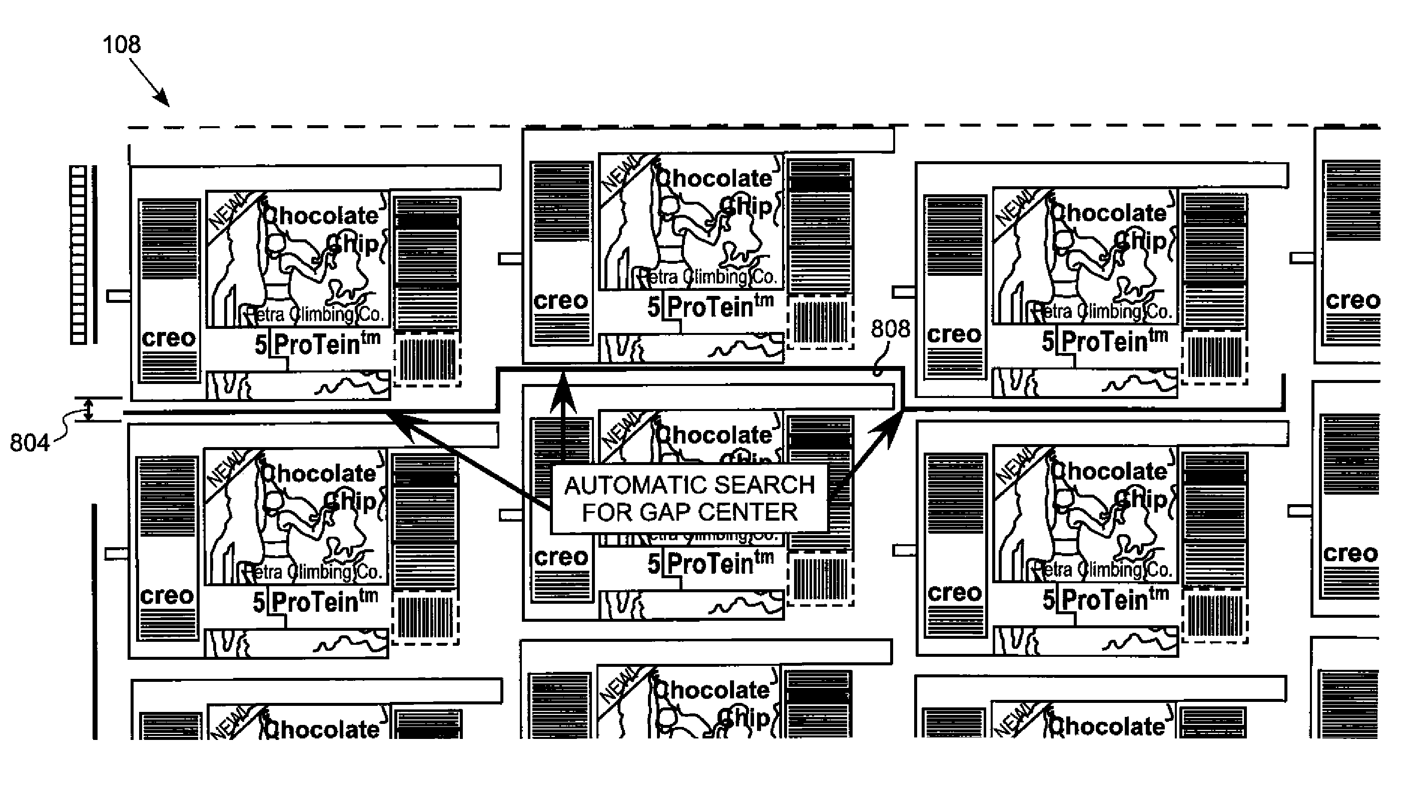
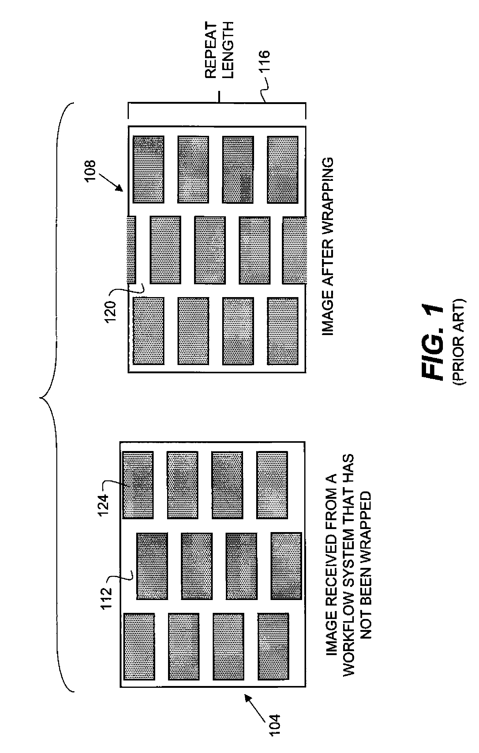
[0040]The present invention is adapted to improve deficiencies in the current workflow process. More specifically it suggests an automatic method to create an optimal cut line for the flexographic plate. In one embodiment of the invention the optimal cut line is created automatically, taking into consideration the data content of the various job separations. The cut line design may take into consideration the step and repeat element structure, thus saving cut line calculation processes. Creation of similar cut lines across different separations is preferable. One of the parameters which are considered during a cut line creation is to design similar cut lines across different separations of a printing job. The parameter is also taken into consideration as well during cut line creation.

[00...


PUM


Abstract

A method for seam for a layout of a packaging printing job (908). The method is adapted to create minimal plate waste (1312) and includes the following steps; providing a wrapped layout (120) comprised of plurality of step and repeat element elements, and analyzing the wrapped layout to produce seam cut line design (1204) for the packaging printing job. The cut line is produced by searching for an non imaged areas inside the images and the borders of the step and repeat elements.

Description

CROSS REFERENCE TO RELATED APPLICATIONS[0001]Reference is made to commonly-assigned U.S. patent application Ser. No. 12 / 025,807 (now U.S. Publication No. 2009 / 0195837), filed Feb. 5, 2008, entitled A METHOD FOR IMAGING FLEXOGRAPHIC PLATES, by Dardikam et al., the disclosure of which is incorporated herein.FIELD OF THE INVENTION[0002]The present invention relates to flexography printing and more specifically to methods and apparatus for designing a sleeve for optimal flexographic plate imaging.BACKGROUND OF THE INVENTION[0003]Flexographic printing plates are relatively expensive compared to other types of plates such as those used in offset printing; therefore, flexographic printers will only use the appropriate amount of plate material necessary to transfer a graphic image. The graphic image is subsequently transferred from the flexographic plate to a substrate such as film, paper, or board, etc. Printers reduce the cost of printing when using flexographic plate material, by not usi...

Claims


Application Information

Patent Timeline
Patent Type & Authority Patents(United States)
IPC IPC(8): H04N1/40
CPCB41C1/184B41N1/16H04N1/3876B41M1/04
Inventor TELEMDARDIKMAN, SHAY
Owner EASTMAN KODAK CO
Learn More