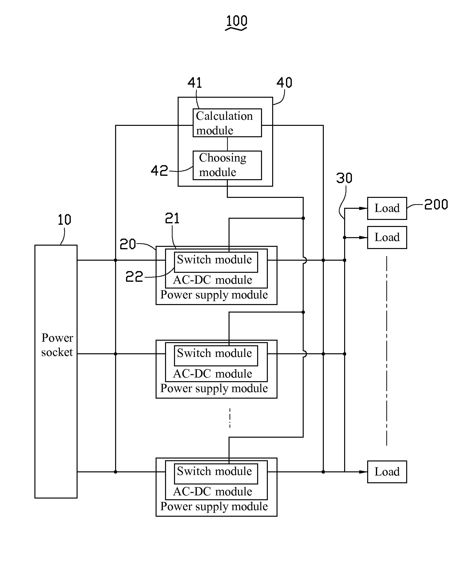
System for maintaining power efficiency of power supply modules by selectively connecting and disconnecting power supply modules from a plurality of power supply modules based on the calculated power supply module output to input ratio of each module
a power supply module and power supply module technology, applied in the field of power supply systems, can solve problems such as waste of part of input power
- Summary
- Abstract
- Description
- Claims
- Application Information
AI Technical Summary
Benefits of technology
Problems solved by technology
Method used
Image


Examples
second embodiment
[0019]Referring to FIG. 2, a power supply system 100a is shown. The difference between the power supply system 100a and the power supply system 100 of the first exemplary embodiment is that the power supply modules 20a includes an AC-DC module 21a and a switch module 22a electrically connected with the AC-DC module 21a. The AC-DC module 21a and the switch module 22a are connected in series between the input terminal and output terminal of the power supply module 20.
third embodiment
[0020]Referring to FIG. 3, a power supply system 100b is shown. The difference between the power supply system 100b and the power supply system 100 of the first exemplary embodiment is that the power supply module 20b further includes a current measuring module 23 connected with the AC-DC module 21b. The control module 40 further includes a store module 43 connected with the calculation module 41. The calculation module 41 connects with the current measuring modules 23 of the power supply module 20b. The choosing module 42 connects with the switch modules 22b of the AC-DC module 21b. The store module 43 pre-stores the input power of the power supply module 20b therein. The calculation module 41 receives currents value from the current measuring modules 23 and calculates the total output power of the power supply modules 20b. The calculation module 41 compares the total output power of the power supply modules 20b with the input power stored in the store module 43. The choosing modu...
fourth embodiment
[0021]Referring to FIG. 4, a power supply system 100c is shown. The difference between the power supply system 100c and the power supply system 100b of the third exemplary embodiment is that the power supply modules 20c includes an AC-DC module 21c and a switch module 22c electrically connected with the AC-DC module 21c. The AC-DC module 21c, the switch module 22c, and the current measuring modules 23 are connected in series between the input terminal and output terminal of the power supply module 20.
PUM
 Abstract
Description
Claims
Application Information