Multistage transmission

a transmission and multi-stage technology, applied in the direction of toothed gearings, gearing elements, gearing rings, etc., can solve the problems of not matching the actual speed and the shift position of the shift drum, and cannot be executed without any means

Active Publication Date: 2013-08-06
HONDA MOTOR CO LTD
View PDF5 Cites 0 Cited by
  • Summary
  • Abstract
  • Description
  • Claims
  • Application Information

AI Technical Summary

Benefits of technology

[0015]According to an embodiment of the present invention, a multistage transmission is provided with a lost motion mechanism that can execute a smooth shift and can regulate operation for a downward shift in acceleration and operation for an upward shift in deceleration.

Problems solved by technology

However, in a downward shift in acceleration and an upward shift in deceleration, as the fitting means the fitting of which is maintained before the shift is not naturally released, the shift cannot be executed without any means.
However, as the control rod is moved by the lost motion mechanism though the shift cannot be executed, a driver (a rider) who operates the shift has a sense of incompatibility for a situation wherein the shift is disenabled though the operation is enabled.
Nevertheless, as the shift drum is turned, a situation wherein a shift position of the shift drum and the actual speed are not matched occurs.

Method used


Image

  • Multistage transmission
  • Multistage transmission
  • Multistage transmission

Examples


Embodiment Construction

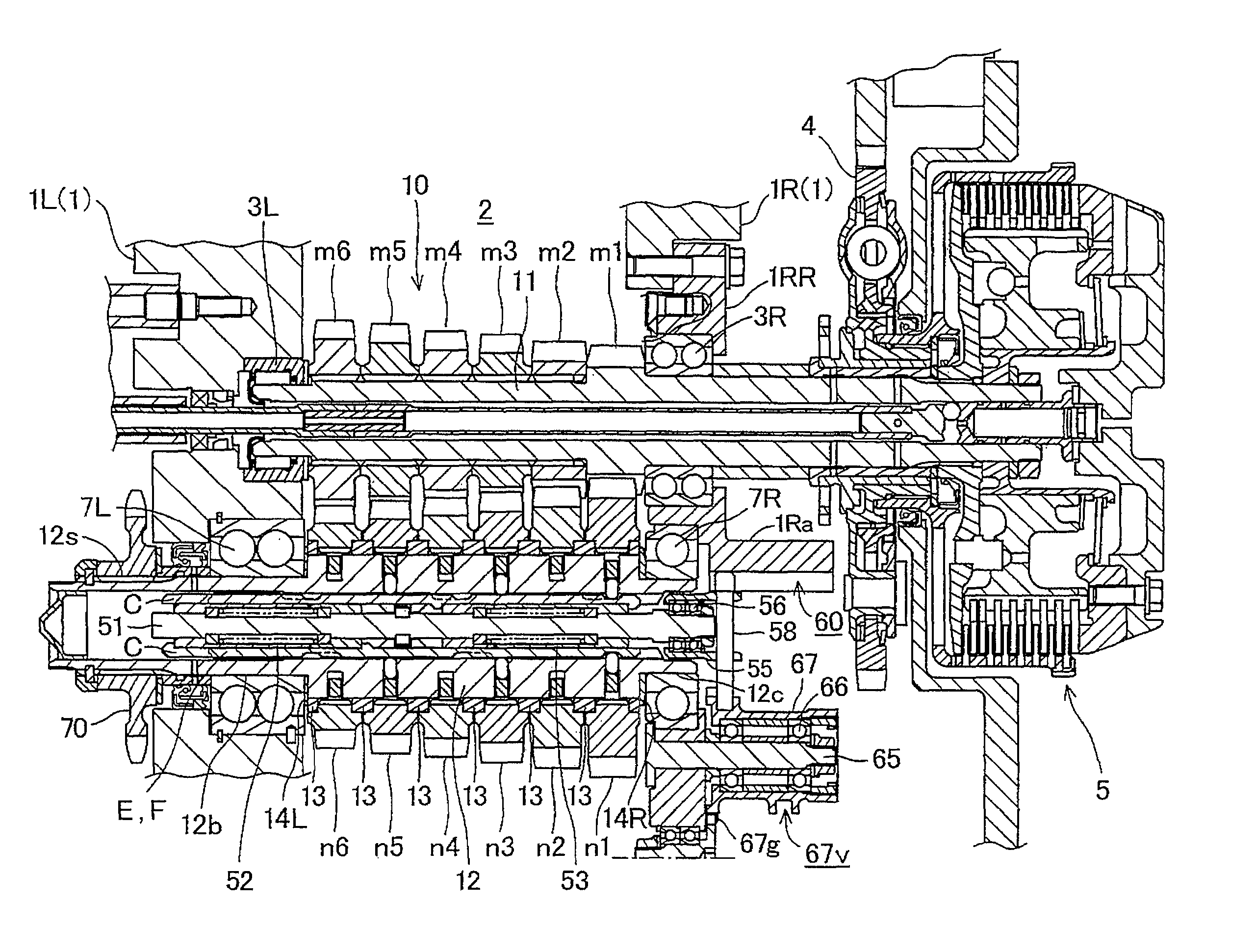
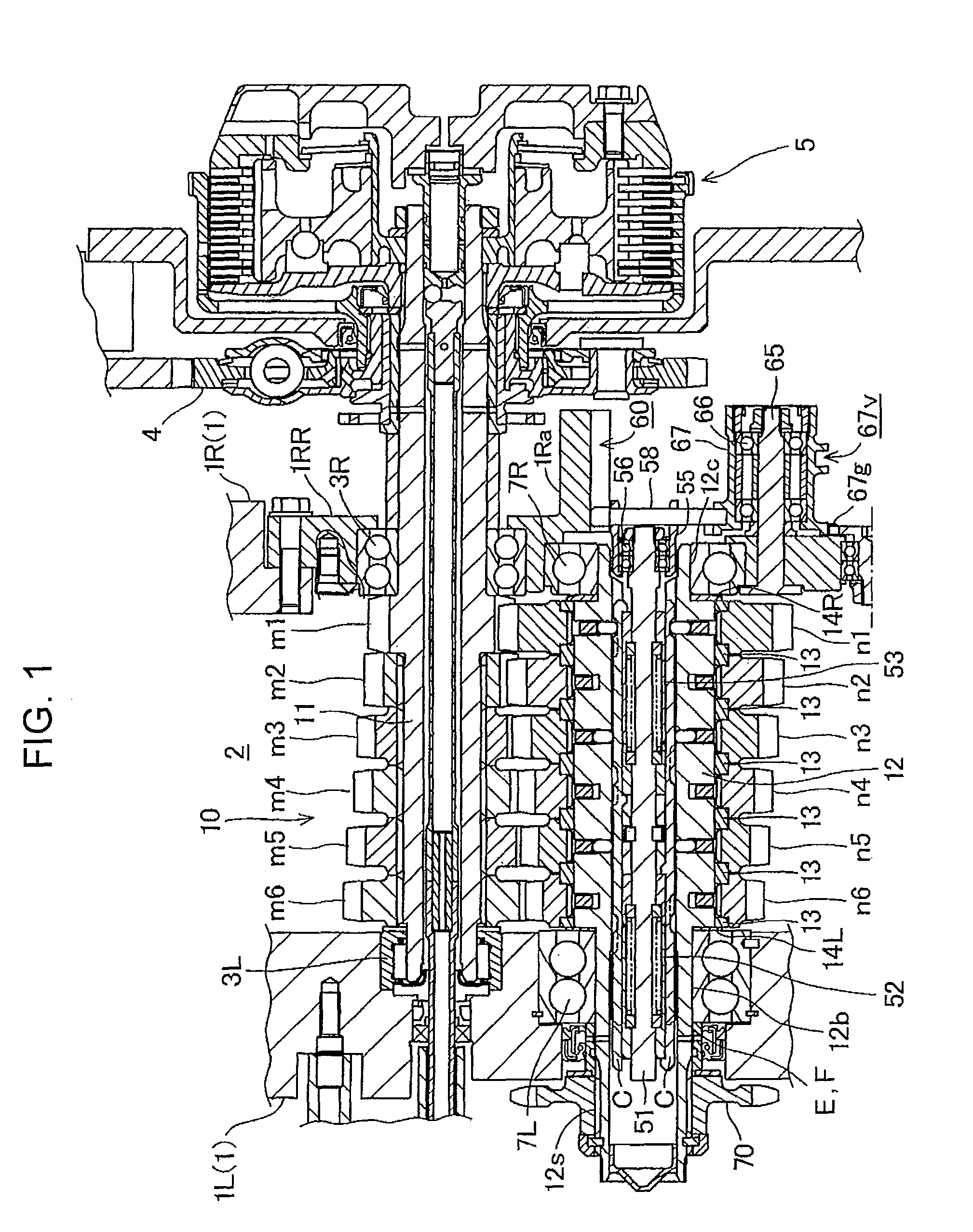
[0074]Referring to FIGS. 1 to 17, the present invention will be described below wherein a multistage transmission 10 is built in an internal combustion engine mounted in a motorcycle.

[0075]FIG. 1 is a sectional view showing the multistage transmission 10 and as shown in FIG. 1, the multistage transmission 10 is provided to an engine casing 1 that also covers the internal combustion engine.

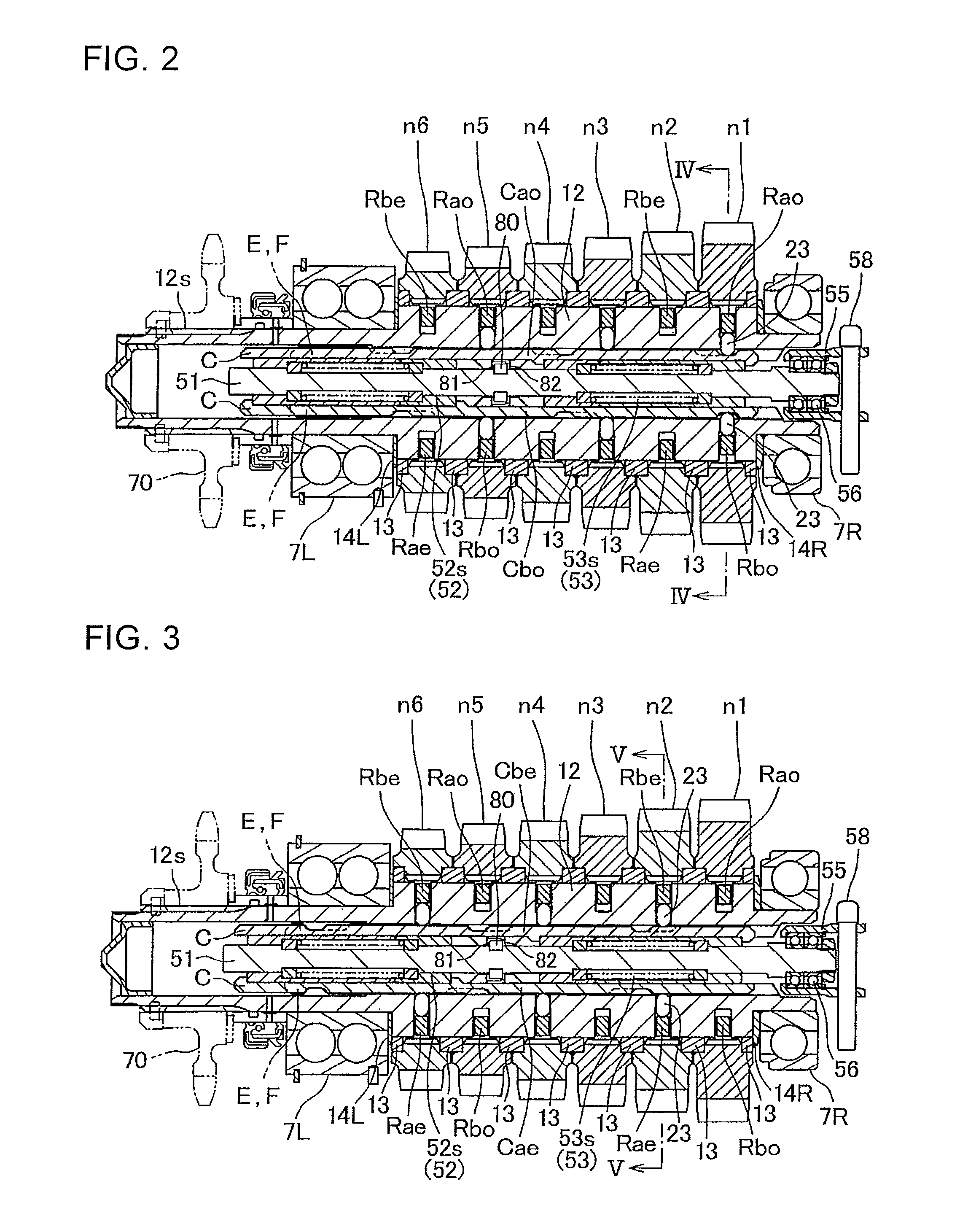
[0076]The engine casing 1 is configured by uniting a left engine casing 1L and a right engine casing 1R, respectively, wherein the laterally divided forms a transmission chamber 2 with a main gear shaft 11 and a counter gear shaft 12 being rotatably journaled to the transmission chamber 2 with the gear shafts laterally laid mutually in parallel.

[0077]The main gear shaft 11 is rotatably journaled to a side wall of the left engine casing 1L and a side wall 1RR of the right engine casing 1R via each bearing 3L, 3R and pierces the right bearing 3R. A multi-disc type friction clutch 5 is provided to its...


PUM


Abstract

A multistage transmission includes a lost motion mechanism for regulating the operation for a downward shift in acceleration and for an upward shift in deceleration. Regulating rods are integrally moved with a control rod. A cutout into which a pin can be fitted together with a cam groove of the slidingly touched cam rod is formed corresponding to each cam groove in the regulating rods. The cutout of the regulating rods corresponding to the cam groove of the cam rod for normal rotation is formed longer than the corresponding cam groove on the reverse side to a moving direction of the control rod in an upward shift in a state in which shifted speed is established. The cutout of the regulating rods corresponding to the cam groove of the cam rod for reverse rotation is formed longer than the corresponding cam groove on the reverse side to a moving direction.

Description

CROSS-REFERENCE TO RELATED APPLICATIONS[0001]The present application claims priority under 35 USC 119 to Japanese Patent Application No. 2009-178504 filed on Jul. 31, 2009 and Japanese Patent Application No. 2009-199219 filed on Aug. 31, 2009 the entire contents of which are hereby incorporated by reference.BACKGROUND OF THE INVENTION[0002]1. Field of the Invention[0003]This invention relates to a multistage transmission in which a plurality of driving gears and a plurality of driven gears are journaled to mutually parallel gear shafts in a constantly engaged state at every speed.[0004]2. Description of Background Art[0005]In this constant-mesh type multistage transmission, either set of the driving gears or the driven gears is fixed to the gear shaft, the other set is turnably journaled to the gear shaft, and a shift is executed by switching gears fitted to the rotated shaft out of turnable gears by fitting means.[0006]The configuration is known by the present applicant wherein a l...

Claims


Application Information

Patent Timeline
Patent Type & Authority Patents(United States)
IPC IPC(8): F16H3/10
CPCF16H3/083Y10T74/19219Y10T74/19279F16H2063/3096
Inventor MATSUMOTO, SHINYA
Owner HONDA MOTOR CO LTD
Why Eureka
Try Eureka